Hyundai Palisade (LX2): Fuel Delivery System / Fuel Pump Motor
Hyundai Palisade (LX2) 2020-2026 Service Manual / Engine Control/Fuel System / Fuel Delivery System / Fuel Pump Motor
Repair procedures
| Removal |
| 1. |
Remove the fuel pump.
(Refer to Fuel Delivery System - "Fuel Pump")
|
| 2. |
Disconnect the electric pump wiring connector (A), and the fuel sender
connector (B).
|
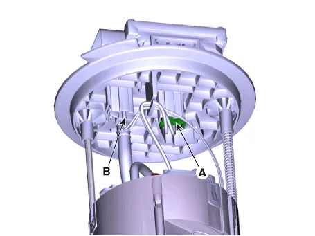
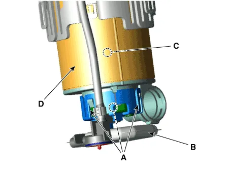
| 3. |
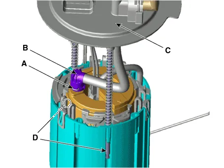
Remove the fixing clip (A), and then disconnect the feed tube (B).
|
| 4. |
Remove the head assembly (C) after releasing the cushion fixing clip
(D).
|
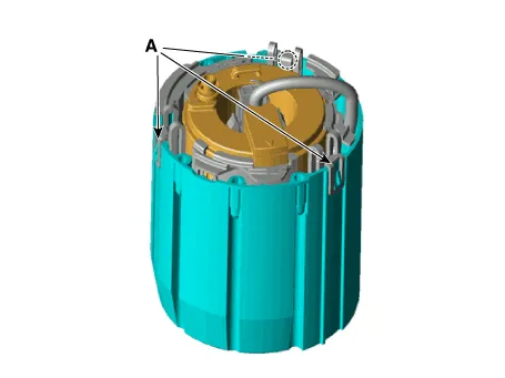
| 5. |
Remove the reservoir-cup after releasing the fixing hook (A).
|
| 6. |
Remove the fuel pressure regulator fixing clip (A).
|
| 7. |
Remove the fuel pressure regulator (B) from the fuel filter.
|
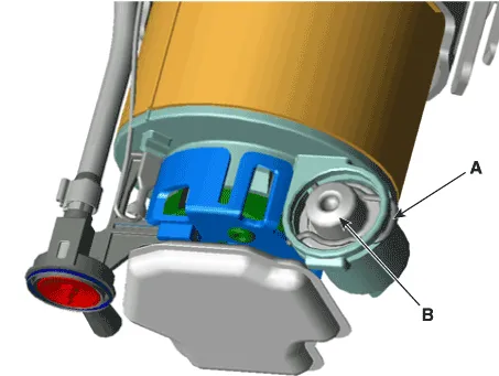
| 8. |
Remove the pre-filter (B) after releasing the fixing hooks (A).
|
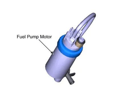
| 9. |
Remove the fuel pump motor (C) from the fuel filter (D) by pulling it
in down direction.
|
| Installation |
| 1. |
Install in the reverse order of removal.
|
Repair procedures Removal 1. Remove the fuel pump. (Refer to Fuel Delivery System - "Fuel Pump") 2.
Repair procedures Removal 1. Remove the fuel pump. (Refer to Fuel Delivery System - "Fuel Pump") 2.
Other information:
Hyundai Palisade (LX2) 2020-2026 Service Manual: Heater & A/C Control Unit (DATC)
Components and components location Component Connector Pin Function Connector PIN No Pin Function Connector PIN No Pin Function A 1 Battery A 21 IGN2 2
Hyundai Palisade (LX2) 2020-2026 Service Manual: Components and components location
Categories
- Manuals Home
- Hyundai Palisade Owners Manual
- Hyundai Palisade Service Manual
- Scheduled maintenance services
- Lift and Support Points
- Electrochromatic Mirror (ECM) with homelink system
- New on site
- Most important about car

Copyright © 2026 www.hpalisadelx.com - 0.012