Hyundai Palisade (LX2): Controller / Heater & A/C Control Unit (DATC)
Components and components location
| Component |

| Connector Pin Function |
|
Connector |
PIN No |
Pin Function |
Connector |
PIN No |
Pin Function |
|
A |
1 |
Battery |
A |
21 |
IGN2 |
|
2 |
ISG B+ |
22 |
IGN1 |
||
|
3 |
ILL+ (TAIL) |
23 |
Blower Motor (+) |
||
|
4 |
Sensor Ground REF (+5V) |
24 |
Photo Sensor (-)_LEFT |
||
|
5 |
Mode Control Actuator Feedback |
25 |
Photo Sensor (-)_RIGHT |
||
|
6 |
Temperature Actuator Feedback - Driver |
26 |
Incar Sensor (+) |
||
|
7 |
Intake Actuator Feedback |
27 |
Incar Motor (-) |
||
|
8 |
Evaporator Temperature Sensor (+) |
28 |
PTC Relay 3 |
||
|
9 |
Ambient Temperature Sensor (+) |
29 |
PTC Relay 3 |
||
|
10 |
Mode Control Actuator (Vent) |
30 |
PTC On Signal |
||
|
11 |
Mode Control Actuator (Defrost) |
31 |
Detent out (-) |
||
|
12 |
Temperature Control Actuator (Cool) - Driver |
32 |
K - Line |
||
|
13 |
Temperature Control Actuator (Warm) - Driver |
33 |
P_CAN High |
||
|
14 |
Intake Actuator (Fresh Air) |
34 |
P_CAN Low |
||
|
15 |
Intake Actuator (Recirculated Air) |
35 |
Mosfet (DRAIN F/B) |
||
|
16 |
HTD (Rear Defrost) |
36 |
Mosfet (GATE) |
||
|
17 |
Rear Defogging Swich |
37 |
ECV + |
||
|
18 |
Clean Signal |
38 |
ECV - |
||
|
19 |
Ionizer Diagnosis |
39 |
Sensor Ground |
||
|
20 |
ILL - (RHEO) |
40 |
Ground |
|
Connector |
PIN No |
Pin Function |
Connector |
PIN No |
Pin Function |
|
B |
1 |
Temperature Control Actuator Feedback - Passenger |
B |
9 |
- |
|
2 |
Temperature Control Actuator (Cool) - Passenger |
10 |
- |
||
|
3 |
Temperature Control Actuator (Warm) - Passenger |
11 |
- |
||
|
4 |
Defogging Actuator Feedback |
12 |
Defogging Sensor TEMP |
||
|
5 |
Defogging Actuator (Open) |
13 |
Defogging Sensor SCK |
||
|
6 |
Defogging Actuator (Close) |
14 |
Defogging Sensor Data |
||
|
7 |
- |
15 |
- |
||
|
8 |
Seat Signal PWM - Driver |
16 |
Ground |
Repair procedures
| Self Diagnosis |
| 1. |
Self-diagnosis process.
|
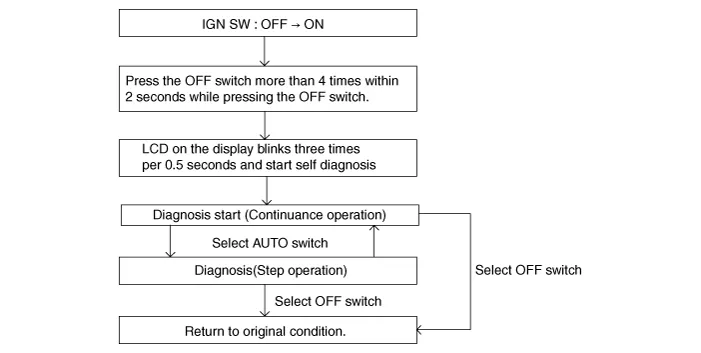

| 2. |
Fault code display
|


| 3. |
|
| 4. |
FAIL SAFE
|
| Replacement |
|

|

| 1. |
Disconnect the negative (-) battery terminal.
|
| 2. |
Using a flat-tip screwdriver or remover and remove the console upper
cover (A).
|

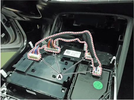
| 3. |
Press the lock pin and separate the various connectors (A).
|
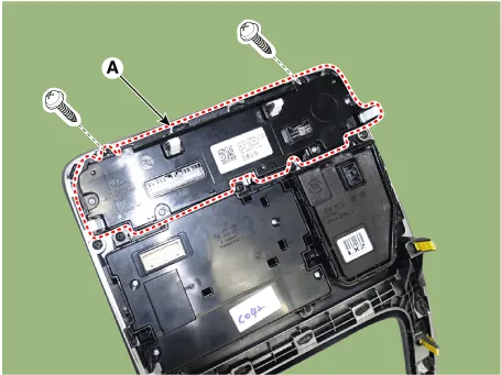
| 4. |
Loosen the mounting screws and remove the heater & A/C control unit
(A).
|
| 5. |
To install, reverse removal procedure.
|

Components and components location Component Connector Pin Function Connector PIN No Pin Function Connector PIN No Pin Function A 1 Battery A 17 IGN2 2 ISG B+ 18 IGN1 3 ILL+ (TAIL) 19 Blower Motor (+) 4 Sensor Ground REF (+5V) 20 - 5 Mode Control Actuator Feedback 21 Mosfet (DRAIN F/B) 6 Temperature Actuator Feedback 22 Mosfet (GATE) 7 Mode Control Actuator (Vent) 23 Heater Switch _ LH 8 Mode Control Actuator (Defrost) 24 Indicator (HIGH) _ LH 9 Temperature Control Actuator (Cool) 25 Indicator (MID) _ LH 10 Temperature Control Actuator (Warm) 26 Indicator (LOW) _ LH 11 Detent out (-) 27 Heater Switch _ RH 12 K - Line 28 Indicator (HIGH) _ RH 13 LIN Left 29 Indicator (MID) _ RH 14 Lin Right 30 Indicator (LOW) _ RH 15 - 31 Sensor Ground 16 ILL - (RHEO) 32 Ground Repair procedures Replacement • When removing with a flat-tip screwdriver or remover, wrap protective tape around the tools to prevent damage to components.
Other information:
Hyundai Palisade (LX2) 2020-2026 Service Manual: PTC Heater (Diesel only)
Description and operation Description The PTC (Positive Temperature Coefficient) heater is installed at the exit or the backside of the heater core. The PTC heater is an electric heater using a PTC element as an auxiliary heating device that supplements deficiency of interior heat source in highly effective diesel engi
Hyundai Palisade (LX2) 2020-2026 Service Manual: Repair procedures
Removal SVM Rear Camera • In case of bad quality or poor focus, be sure to check the camera lense surface condition and foreign materials.
Categories
- Manuals Home
- Hyundai Palisade Owners Manual
- Hyundai Palisade Service Manual
- Electrochromatic Mirror (ECM) with homelink system
- Rain Sensor
- Body Electrical System
- New on site
- Most important about car
