Hyundai Palisade (LX2): Fuel Delivery System / Fuel Pump
Repair procedures
| Inspection |
| 1. |
Turn ignition switch OFF and disconnect the negative (-)battery cable.
|
| 2. |
Remove the fuel pump assembly.
|
| 3. |
Check motor operation by fuel pump connector (A) connecting power (No.1)
and ground (No.6).
|
| 4. |
Also check that the resistance changes smoothly when the float is moved
from "E" to "F".
|
| Removal |
| 1. |
Release the residual pressure in fuel line.
(Refer to Fuel Delivery System - "Release Residual Pressure in Fuel
Line")
|
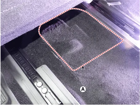
| 2. |
Remove the floor carpet service cover (A).
|
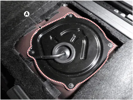
| 3. |
Remove the fuel pump service cover (A) after loosening the mounting
screws.
|
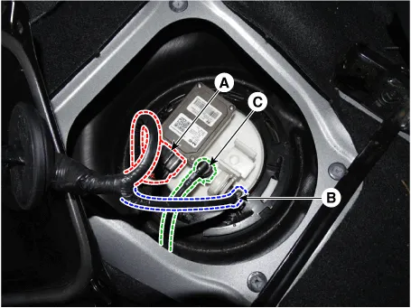
| 4. |
Disconnect the fuel pump control module connector (A) and fuel pressure
sensor connector (B).
|
| 5. |
Disconnect fuel feed tube quick-connector (C).
|
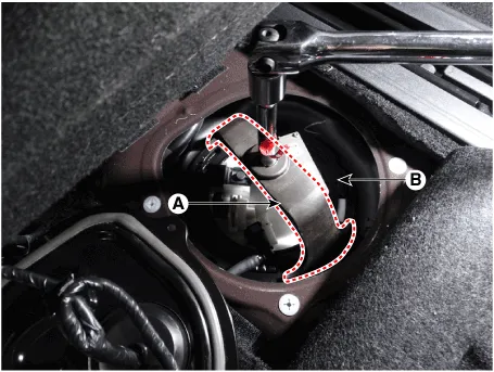
| 6. |
Remove the locking ring (A) by using the special service tool [No.:
09310-B8100].
|

| 7. |
Remove the fuel pump from the fuel tank.
|

| Installation |
| 1. |
Install in the reverse order of removal.
|
Repair procedures • Be careful not to damage the parts located under the vehicle (floor under cover, fuel filter, fuel tank and canister) when raising the vehicle using the lift.
Description and operation Description The fuel pump control module (FPCM) is installed on the right side of the fuel tank and controls the DC motor mounted inside the low pressure fuel pump.
Other information:
Hyundai Palisade (LX2) 2020-2026 Service Manual: A/C Pressure Transducer
Description and operation Description The A/C Pressure Transducer (APT) converts the pressure value of high pressure line into voltage value after measuring it. By converted voltage value, engine ECU controls the cooling fan by operating it high speed or low speed.
Hyundai Palisade (LX2) 2020-2026 Service Manual: Repair procedures
Inspection Tolerance Compensation Tolerance compensation compensates for the error margins of around view video that occur due to the installation tolerance when the four cameras that comprise the SVM system are installed. You must carry out tolerance compensation if you do any of the following.
Categories
- Manuals Home
- Hyundai Palisade Owners Manual
- Hyundai Palisade Service Manual
- Automatic Transaxle System (A8LF1)
- How to reset the power liftgate
- Automatic Transaxle Fluid (ATF)
- New on site
- Most important about car
