Hyundai Palisade: Surround View Monitor (SVM) / Description and operation
Hyundai Palisade (LX2) 2020-2025 Service Manual / Advanced Driver Assistance System (ADAS) / Surround View Monitor (SVM) / Description and operation
| Description |
Surround View Monitor (SVM) is the system that allows video monitoring of 360
degrees around the vehicle. The system includes 4 ultra optical camera mounted
around the vehicle (front, both sides, rear).
The video from these cameras are applied with distortion compensation, time
point conversion, and video merging technologies to provide sky-view image of
the vehicle's surrounding area, as well as various other view modes.
The SVM System provides video feed of the vehicle's surrounding area while parking
or during low speed driving to the driver to enhance safety and driver's convenience.
In addition, the system also displays video image of vehicle's surrounding area,
and includes steering wheel synchronized guide line indication, front and rear
object warning, and A/S (including In-Line) tolerance compensation features.
It's a system that displays the video, from ultra optical cameras mounted on
4 sides of the vehicle, on the Head Unit Screen. It shows 360 degrees sky-view
image of the vehicle's surrounding area, as well as various other view modes.
The SVM System provides video feed of the vehicle's surrounding area while the
vehicle is parked or during low speed driving to the driver to enhance safety
and driver's convenience.
Blind-spot View Monitor (BVM)
Blind-spot View Monitor (BVM) is a driving safety system that helps provide
a more comprehensive views on areas which is not usually visible by the side
mirrors when the vehicle tries to change the lane.
|
The BVM system provides a driver a more comprehensive view which is
not usually visible by the side mirrors in certain situations like swithing
drive lanes. The system helps to avoid any blind spot mishaps.
|
| – |
The rear side view is displayed in the cluster screen when the turning
lights are in operation as the light switch goes up and down by the
driver.
|
| – |
The SVM also provides an edited view of the left side/ right side without
adding more cameras.
|
| – |
It helps minimize the distraction of the driver by displaying the rear
side view that is usually hard to see.
|
|

| Major Features |
| 1. |
Display Vehicles Surrounding in Video
The surrounding area video display function displays the 360 degrees
video image captured through 4 cameras to the driver through the Head
Unit Screen while the vehicle is moving at low speed or going reverse.
The SVM System displays total of 8 video modes for displaying surrounding
video based on the vehicle driving state and the driver's selection.
|
| 2. |
Guide Line Indication & Steering Wheel Synchronized Feature
The Guide Line Indication & Steering Wheel Synchronized Feature is the
function that assists the driver in parking by synchronizing the steering
wheel with the rear view video display marked with a guide line to help
anticipate the direction of the vehicle going reverse.
|
| 3. |
Front/Rear Object Warning (Obstacle Detection Feature)
The system receives obstacle warning signal from the PAS or SPAS sensors
mounted on the front/rear of the vehicle and displays the obstacle location
on the SVM Head Unit Screen.
|
| 4. |
Tolerance Compensation (including A/S)
Manual Tolerance Compensation Software is embedded in the SVMECM to
compensate the SVM deviation that may occur due to assembly line installation
tolerance. You must first setup proper work environment in order to
perform correct tolerance compensation.
|
Main Features
|
No |
Main Features |
Detailed Description |
Notes |
||||||
|
1 |
8 View Mode Display |
|
Merged Video Display of 8 Modes |
||||||
|
2 |
Front Assist Mode Selection Feature |
|
Same as the PAS SVM Switch |
||||||
|
3 |
Rear Steering Synchronized Parking Guide Line Display |
|
Display over the Rear Video |
||||||
|
4 |
PAS Obstacle Indication |
|
Display both on the Cluster and the Head Unit |
||||||
|
5 |
User Setting Option |
|
Provides additional screen settings |
||||||
|
6 |
Assembly Line & A/S Tolerance Compensation Feature |
|
Compensation function recognition logic applied |
SVM Mode Entry Conditions
The vehicle information is accessed regularly, even after entering SVM mode.
When the conditions are met, conversion from front mode to rear mode is available,
and vice versa.
When the mode is converted, the view displayed on the screen can be the initial
view or the previous view depending on the conditions.
If the mode for conversion is the initial entry, the default view is selected
based on the front or rear. If a continuous front-rear conversion mode occurs
as forward and backward movement are repeated for parking, the previous view
is recalled and displayed.
| – |
Initial Entry: When the rear and front mode view in SVM mode is displayed
on the screen for the first time
|
| – |
Re-entry: When switching from SVM mode to another mode, without turning
off SVM, and returning to the previous mode
(e.g. Rear → Front → Rear: Re-enter rear mode / Front → Rear → Front:
Re-enter front mode)
|
|
Switch mode |
Vehicle speed |
Gear |
SVM Switch |
Display view |
|
Rear → Front |
below 20 kph |
R Range or P Range excluded |
ON |
Initial Entry: Front view set in the initial view mode option |
|
Re-entry: The last view mode displayed in the previous front mode |
||||
|
Front → Rear |
Irrelevant |
Reverse Gear |
Irrelevant |
Initial Entry: Rear view set in the initial view mode option |
|
Re-entry: The last view mode displayed in the previous rear mode |
SVM Mode Disengagement
If the conditions below are satisfied while in SVM mode, the SVM is turned OFF
and no video is displayed.
|
OFF Mode |
Vehicle speed |
Gear |
SVM Switch |
Notes |
|
Front mode |
over 20 kph |
R Range or P Range |
OFF |
If any of the three conditions are satisfied |
|
Rear mode |
Irrelevant |
Except R gear |
Irrelevant |
If any of the two conditions are satisfied |
SVM Options
Considering the user's convenience, the SVM provides three options for the user
to select.
The window for changing options (parking guide settings) is displayed by the
AVN. Only the changed options are forwarded to the SVM unit through M_CAN.
These three options are applied as soon as they have been selected by the user.
Based on the conditions, the initial views displayed are as follows.
|
Option |
Function |
Default setting |
|
Guideline steering interlocking |
Interlocks with steering to display the driving direction of the vehicle
during parking. |
Classification code |
|
Close range warning indicator |
Indicates front and rear obstacle detection |
Classification code |
|
Initial view mode setting |
Default view displayed when entering SVM mode |
Front + around view |
|
Rear + around view |
Operations for Guideline Steering Interlocking Indications
The indication for the guideline steering interlocking trace uses the steering
wheel angle value periodically received by the SVM unit through C-CAN.
A rear area that displays a 130 degree image of the rear mode (two-split mode)
and a wide view are displayed with the expected car movement trace.
| 1. |
View modes for guideline steering interlocking indications
|
| 2. |
Specifications for guideline steering interlocking trace lines
|
| 3. |
Indications for neutral trace lines
If the steering angle is neutral, the neutral trace line is indicated
in blue, which shows the expected movement trace of the car.
This line is displayed with the guideline steering interlocking trace
line and is also a fixed line that is not interlocked with the steering
angle operation.
|
SVM system input/output
| 4. |
Camera input
|
||||||||||||||||||
| 5. |
SVM image display
The images received from the 4 cameras mounted on the vehicle go through
the image distortion correction logic and the image merging process.H/UNIT
displays these images toghether with other additional features such
as the parking guidelines linked with steering wheel on the AVN screen.
|
| 6. |
Parking/view button
It is used as a control input signal to operate the front view mode
function with the ignition switch ON.
|
| 7. |
Ignition input
SVM unit displays the image only in the IGN2 ON and limits the image
display with the SVM OFF in the IGN2 OFF.
SVM unit uses the signal which is input to the IGN pin or M-CAN message
routed from the IGPM (gateway) to C-CAN to judge the IGN2 ON/OFF.
|
| 8. |
Switch indicator display
SVM unit displays the LED power inside the SVM switch in the form of
PWM waves to inform the user whether SVM switch is pressed.
|
| 9. |
Chassis CAN input (C_CAN)
SVM unit receives the vehicle state information through the C_CAN to
determine the operation of SVM major functions.
|
| 10. |
Multimedia CAN input/output
Relevant information is processed by receiving the M-CAN signal routed
from the IGPM (gateway) to C-CAN.
The routed M-CAN signal communication aims to transmit and receive the
below information.
|

 Repair procedures
Inspection
Tolerance Compensation
Tolerance compensation compensates for the error margins of around view video
that occur due to the installation tolerance when the four cameras that comprise
the SVM system are installed...
Other information:
Hyundai Palisade (LX2) 2020-2025 Service Manual: Components and components location
Components 1. Supplemental Restraint System Control Module (SRSCM) 2. Rear Gravity side Impact Sensor (G-SIS) 3. Front Gravity side Impact Sensor (G-SIS) 4. Front impact sensor (FIS) 5. Front impact sensor (FIS) 6...
Hyundai Palisade (LX2) 2020-2025 Service Manual: Temperature Control Actuator
Description and operation Description The heater unit includes mode control actuator and temperature control actuator. The temperature control actuator is located at the heater unit. It regulates the temperature by the procedure as follows...
Categories
- Manuals Home
- 1st Generation Palisade Owners Manual
- 1st Generation Palisade Service Manual
- Reverse Parking Aid Function
- How to reset the power liftgate
- AWD Operation
- New on site
- Most important about car
Battery replacement
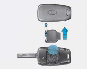
If the remote key is not working properly, try replacing the battery with a new one.
Battery Type: CR2032
To replace the battery:

Copyright © 2025 www.hpalisadelx.com