Hyundai Palisade (LX2): Engine Control System / CVVT Oil Control Valve (OCV)
Description and operation
Continuous Variable Valve Timing (CVVT) system advances or retards the valve
timing of the intake and exhaust valve in accordance with the ECM control signal
which is calculated by the engine speed and load.
By controlling CVVT, the valve overlap or underlap occurs, which in turn improves
fuel efficiency, reduces exhaust gases (NOx, HC) and improves engine performance
by reducing pumping loss, generating internal EGR effect, improving combustion
stability, improving volumetric efficiency and increasing expansion work.
This system consists of the CVVT Oil Control Valve (OCV) which supplies the
engine oil to the cam phaser or spills the engine oil from the cam phaser in
accordance with the ECM PWM (Pulse With Modulation) control signal, the CVVT
Oil Temperature Sensor (OTS) which measures the engine oil temperature, and
the Cam Phaser which varies the cam phase by using the hydraulic force of the
engine oil.
The engine oil which is supplied through the CVVT oil control valve varies the
cam phase in the direction (Intake Advance/Exhaust Retard) or opposite direction
(Intake Retard/Exhaust Advance) of the engine rotation by rotating the rotor
connected with the camshaft inside the cam phaser.
CVVT Oil Control Valve (OCV) [Banks 1, 2 / Exhaust]
Specifications
Item
|
Specification
|
Coil Resistance (Ω)
|
6.9 - 7.9 [20°C (68°F)]
|
Troubleshooting
Schematic diagrams
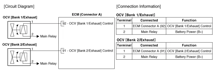
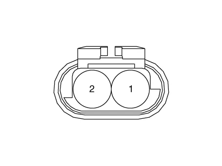
Harness Connector
Repair procedures
| 1. |
Switch "OFF" the ignition.
|
| 2. |
Disconnect the OCV connector.
|
| 3. |
Measure resistance between the OCV terminals 1 and 2.
|
| 4. |
Check that the resistance is within the specification.
|
Specification : 6.9 - 7.9Ω [20°C (68°F)]
|
|
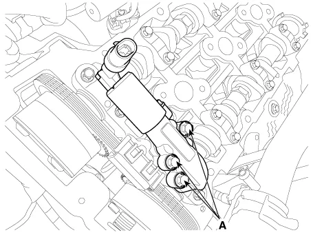
CVVT Oil Control Valve [Bank 1 / Exhaust]
| 1. |
Switch "OFF" the ignition and disconnect the negative (-) battery terminal.
|
| 2. |
Remove the cylinder head cover.
(Refer to Engine Mechanical System - "Cylinder Head Assembly")
|
| 3. |
Remove the installation bolt (A), and then remove the valve from the
engine.
|
CVVT oil control valve mounting bolt :
9.8 - 11.8 N.m (1.0 - 1.2 kgf.m, 7.2 - 8.7 lb-ft)
|
|
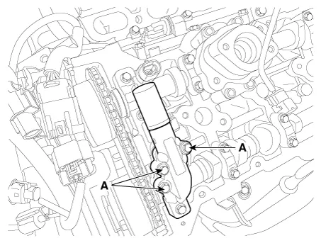
CVVT Oil Control Valve [Bank 2 / Exhaust]
| 1. |
Switch "OFF" the ignition and disconnect the negative (-) battery terminal.
|
| 2. |
Remove the cylinder head cover.
(Refer to Engine Mechanical System - "Cylinder Head Assembly")
|
| 3. |
Remove the installation bolt (A), and then remove the valve from the
engine.
|
CVVT oil control valve mounting bolt :
9.8 - 11.8 N.m (1.0 - 1.2 kgf.m, 7.2 - 8.7 lb-ft)
|
|
| • |
Install the component to the specified torque.
|
| • |
Note that internal damage may occur if the component drops.
In this case, inspect it before installation.
|
| • |
Apply the engine oil to the valve O-ring.
|
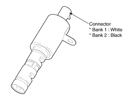
| • |
Exactly distinguish the color of the valve and harness connectors
in banks 1 and 2 when installing, or the engine will operate
abnormally (Refer to the table below).
|
|
Items
|
Component Side
|
Harness Side
|
Bank 1 (RH)
|
Grey
|
Bank 2 (LH)
|
Black
|
| 1. |
Install in the reverse order of removal.
|
Description and operation
Description
Continuous Variable Valve Timing (CVVT) system advances or retards the valve
timing of the intake and exhaust valve in accordance with the ECM control signal
which is calculated by the engine speed and load.
Description and operation
Description
Installed on the intake manifold (VIS Valve 1) and the surge tank (VIS Valve
2), the Variable Intake manifold Solenoid (VIS) valves 1 and 2 control the vacuum
modulators, which activate the valves in the intake manifold and the surge tank.
Other information:
Description and operation
Description
The heater unit includes mode control actuator and temperature control actuator.
The temperature control actuator is located at the heater unit. It regulates
the temperature by the procedure as follows.
Schematic diagrams
Schematic Diagrams
Repair procedures
Removal
1.
Remove the bumper cover.
(Refer to Body - "Front Bumper Cover")
(Refer to Body - "Rear Bumper Cover")
2.

