Hyundai Palisade: Engine Control System / Variable Intake Solenoid (VIS) Valve
Description and operation
Installed on the intake manifold (VIS Valve 1) and the surge tank (VIS Valve
2), the Variable Intake manifold Solenoid (VIS) valves 1 and 2 control the vacuum
modulators, which activate the valves in the intake manifold and the surge tank.
These valves open or close according to engine condition. (Refer to below table.)
Specifications
Item
|
Specification
|
Coil Resistance (Ω)
|
30.0 - 35.0 [20°C (68°F)]
|
Schematic diagrams
Harness Connector
Repair procedures
| 1. |
Switch "OFF" the ignition.
|
| 2. |
Disconnect the VIS valve connector.
|
| 3. |
Measure resistance between the VIS valve terminals 1 and 2.
|
| 4. |
Check that the resistance is within the specification.
|
Specification : 30.0 - 35.0Ω [20°C (68°F)]
|
|
[VIS #1]
| 1. |
Switch "OFF" the ignition and disconnect the negative (-) battery terminal.
|
| 2. |
Disconnect the variable intake solenoid valve connector (A).
|
| 3. |
Disconnect the vacuum hoses (B) from the valve.
|
| 4. |
Remove the mounting nut (C) and then remove the valve from the surge
tank.
|
Variable intake solenoid valve mounting nut :
7.8 - 11.8 N.m (0.8 - 1.2 kgf.m, 5.8 - 8.7 lb-ft)
|
|
[VIS #2]
| 1. |
Switch "OFF" the ignition and disconnect the negative (-) battery terminal.
|
| 2. |
Disconnect the variable intake solenoid valve connector (A).
|
| 3. |
Disconnect the vacuum hoses (B) from the valve.
|
| 4. |
Remove the installation nuts (C) and then remove the valve from the
surge tank.
|
Variable intake solenoid valve mounting nut :
7.8 - 11.8 N.m (0.8 - 1.2 kgf.m, 5.8 - 8.7 lb-ft)
|
|
| • |
Install the component to the specified torque.
|
| • |
Note that internal damage may occur if the component drops.
In this case, inspect it before installation.
|
|
| • |
Keep foreign materials away from flowing into the valve.
|
|
| 1. |
Install in the reverse order of removal.
|
Description and operation
Description
Continuous Variable Valve Timing (CVVT) system advances or retards the valve
timing of the intake and exhaust valve in accordance with the ECM control signal
which is calculated by the engine speed and load...
Description and operation
Description
Installed on the high pressure fuel pump, the Fuel Pressure Regulator Valve
controls the fuel amount flowing into the injectors in accordance with the ECM
signal calculated based on various engine conditions...
Other information:
The remote key will not work if any of
the following occur:
The key is in the ignition switch.
You exceed the operating distance
limit (about 90 feet [30 m]).
The remote key battery is weak.
Other vehicles or objects may be
blocking the signal...
During power opening and closing if
the power liftgate is blocked by an
object or part of the body, the power
liftgate may be able to detect the
resistance.
If resistance is detected while opening
or closing the power liftgate, the
liftgate will stop and move in the
opposite direction...
Categories
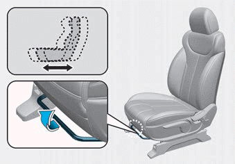
The front seat can be adjusted by
using the levers located on the outside
of the seat cushion. Before driving,
adjust the seat to the proper
position so that you can easily control
the steering wheel, foot pedals
and controls on the instrument
panel.
read more


 CVVT Oil Control Valve (OCV)
 Fuel Pressure Control Valve (FPCV)