Hyundai Palisade (LX2): Cylinder Block / Crankshaft
Repair procedures
| Disassembly |
|

|

|

| 1. |
Remove the engine assembly from the vehicle.
(Refer to Engine and Transaxle Assembly - "Engine And Transaxle Assembly")
|
| 2. |
Remove the transaxle assembly from the engine assembly.
(Refer to Automatic Transaxle System - "Automatic Transaxle")
|
| 3. |
Remove the drive plate and adapter plate.
(Refer to Cylinder Block - "Drive Plate")
|
| 4. |
Remove the rear oil seal case.
(Refer to Cylinder Block - "Rear Oil Seal")
|
| 5. |
Install the engine assembly to engine stand for disassembly.
|
| 6. |
Remove the surge tank.
(Refer to Intake and Exhaust System - "Surge Tank")
|
| 7. |
Remove the intake manifold.
(Refer to Intake and Exhaust System - "Intake Manifold")
|
| 8. |
Remove the exhaust manifold.
(Refer to Intake and Exhaust System - "Exhaust Manifold")
|
| 9. |
Remove the timing chain.
(Refer to Timing System - "Timing Chain")
|
| 10. |
Remove the water temperature control assembly.
(Refer to Cooling System - "Water Temperature Control Assembly")
|
| 11. |
Remove the cylinder head assembly.
(Refer to Cylinder Head Assembly - "Cylinder Head")
|
| 12. |
Remove the lower oil pan and upper oil pan.
(Refer to Lubrication System - "Oil Pan")
|
| 13. |
Remove the oil pump.
(Refer to Lubrication System - "Oil Pump")
|
| 14. |
Remove the oil filter body.
(Refer to Lubrication System - "Oil filter body")
|
| 15. |
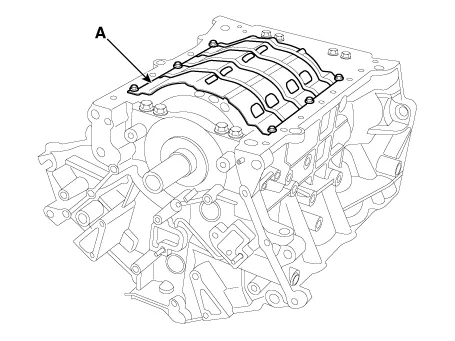
Remove the baffle plate (A).
|
| 16. |
Check the connecting rod end play.
(Refer to Cylinder Block - "Piston and Connecting Rod")
|
| 17. |
Check the connecting rod cap oil clearance.
(Refer to Cylinder Block - "Piston and Connecting Rod")
|
| 18. |
Remove the piston and connecting rod assemblies.
(Refer to Cylinder Block - "Piston and Connecting Rod")
|
| 19. |
Remove the crankshaft main bearing cap and check oil clearance.
|
| 20. |
Check the crankshaft end play.
|
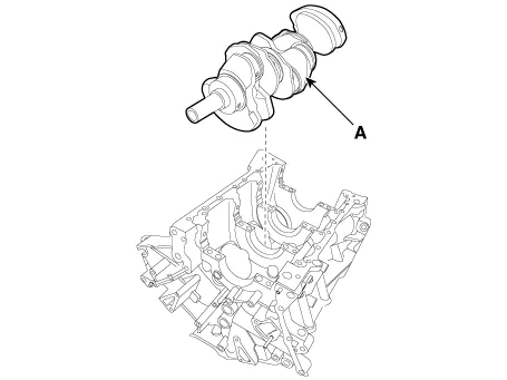
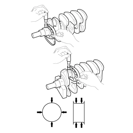
| 21. |
Remove the crankshaft. Lift the crankshaft (A) out of engine, being
careful not to damage journals.
|

| Inspection |
| 1. |
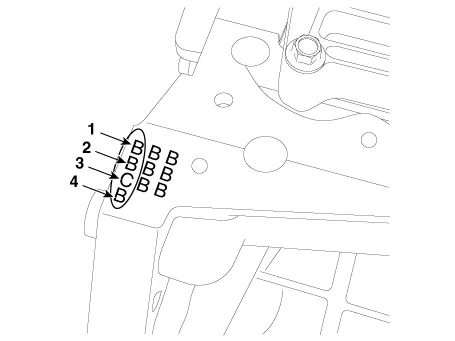
Check the crankshaft bearing oil clearance.
|
|||||||||||||||||||||||||||||||||||||||||||||||||||||||||||||||||||||||||||||||||||||||||||||||||||||||||

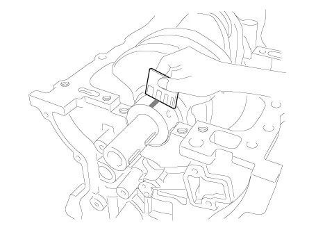


| 2. |
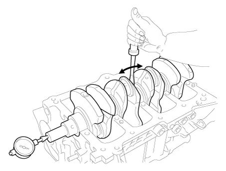
Check crankshaft end play.
Using a dial indicator, measure the thrust clearance while prying the
crankshaft back and forth with a screwdriver.
If the end play is greater than maximum, replace the thrust bearings
as a set.
|
| 3. |
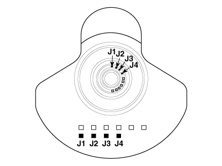
Inspect main journals and crank pins
Using a micrometer, measure the diameter of each main journal and crank
pin.
|
| Reassembly |
|

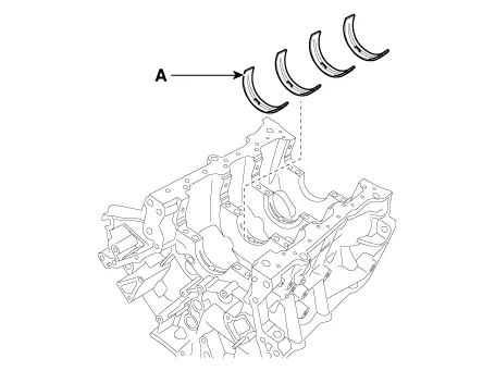
| 1. |
Install the main bearings.
|

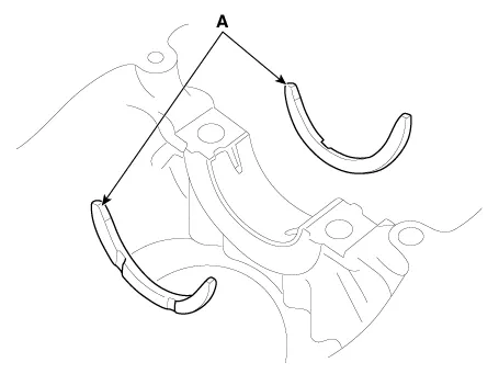
| 2. |
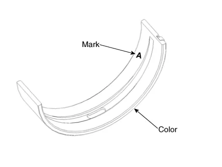
Install the thrust bearings.
Install the 2 thrust bearings (A) under the No. 3 journal position of
the cylinder block with the oil grooves facing outward.
|
| 3. |
Place the crankshaft (A) on the cylinder block.
|

| 4. |
Place the main bearing caps on cylinder block.
|
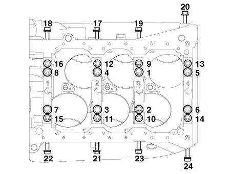
| 5. |
Install the main bearing cap bolts.
|


| 6. |
Check crankshaft end play.
|
| 7. |
Install the piston and connecting rod assemblies.
(Refer to Cylinder Block - "Piston and Connecting Rod")
|
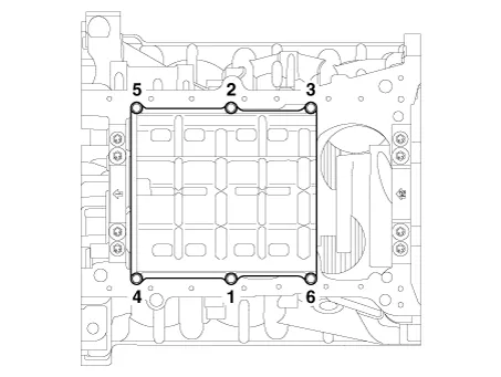
| 8. |
Install the baffle plate.
Install and uniformly tighten the baffle plate bolts, in several passes,
in the sequence shown.
|
| 9. |
Assemble the remaining parts in the reverse order of disassembly.
|

Repair procedures Disassembly • Be careful not to damage the parts located under the vehicle (floor under cover, fuel filter, fuel tank and canister) when raising the vehicle using the lift.
Repair procedures Disassembly • Be careful not to damage the parts located under the vehicle (floor under cover, fuel filter, fuel tank and canister) when raising the vehicle using the lift.
Other information:
Hyundai Palisade (LX2) 2020-2026 Service Manual: Front View Camera Unit
Schematic diagrams Circuit Diagram Repair procedures Removal 1. Disconnect the negative (-) battery terminal. 2. Remove the inside rear view mirror cover (A) and rain sensor cover (B).
Hyundai Palisade (LX2) 2020-2026 Service Manual: Description and operation
Description The smart cruise control system allows a driver to program the vehicle to control the speed and following distance by detecting the vehicle ahead without depressing the brake pedal or the accelerator pedal. 1.
Categories
- Manuals Home
- Hyundai Palisade Owners Manual
- Hyundai Palisade Service Manual
- Emergency liftgate safety release
- Lift and Support Points
- Automatic Transaxle System (A8LF1)
- New on site
- Most important about car
