Hyundai Palisade (LX2): Cylinder Block / Piston and Connecting Rod
Repair procedures
| Disassembly |
|

|

|

| 1. |
Remove the engine assembly from the vehicle.
(Refer to Engine and Transaxle Assembly - "Engine And Transaxle Assembly")
|
| 2. |
Remove the transaxle assembly from the engine assembly.
(Refer to Automatic Transaxle System - "Automatic Transaxle")
|
| 3. |
Remove the drive plate and adapter plate.
(Refer to Cylinder Block - "Drive Plate")
|
| 4. |
Remove the rear oil seal case.
(Refer to Cylinder Block - "Rear Oil Seal")
|
| 5. |
Install the engine assembly to engine stand for disassembly.
|
| 6. |
Remove the surge tank.
(Refer to Intake and Exhaust System - "Surge Tank")
|
| 7. |
Remove the intake manifold.
(Refer to Intake and Exhaust System - "Intake Manifold")
|
| 8. |
Remove the exhaust manifold.
(Refer to Intake and Exhaust System - "Exhaust Manifold")
|
| 9. |
Remove the timing chain.
(Refer to Timing System - "Timing Chain")
|
| 10. |
Remove the water temperature control assembly.
(Refer to Cooling System - "Water Temperature Control Assembly")
|
| 11. |
Remove the cylinder head assembly.
(Refer to Cylinder Head Assembly - "Cylinder Head")
|
| 12. |
Remove the lower oil pan and upper oil pan.
(Refer to Lubrication System - "Oil Pan")
|
| 13. |
Remove the oil pump.
(Refer to Lubrication System - "Oil Pump")
|
| 14. |
Remove the oil filter body.
(Refer to Lubrication System - "Oil filter body")
|
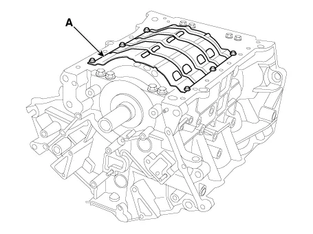
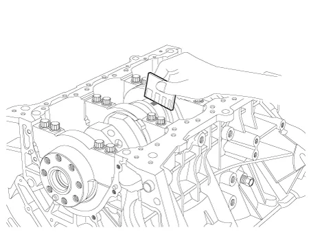
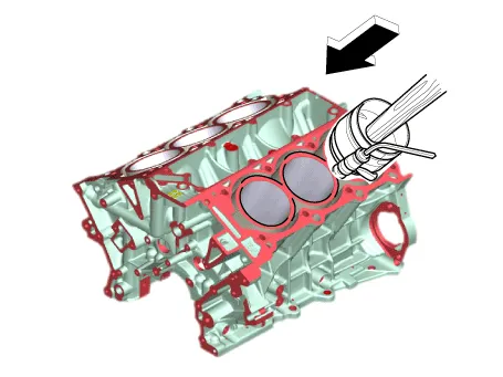
| 15. |
Remove the baffle plate (A).
|
| 16. |
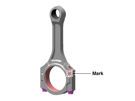
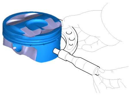
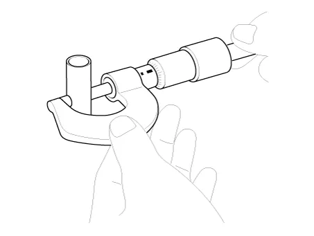
Check the connecting rod end play.
|
| 17. |
Check the connecting rod cap oil clearance.
|
| 18. |
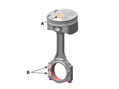
Detach the piston and connecting rod assemblies from the cylinder block.
|


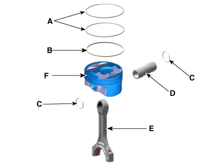
| 19. |
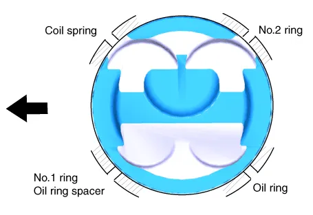
Disassemble the piston rings.
|

| 20. |
Disassemble the connecting rod from the piston.
|
| Inspection |
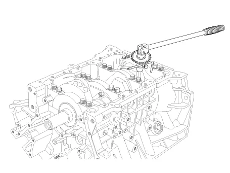
| 1. |
Check the connecting rod end play.
Using a feeler gauge, measure the end play while moving the connecting
rod back and forth.
|
| 2. |
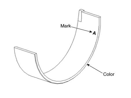
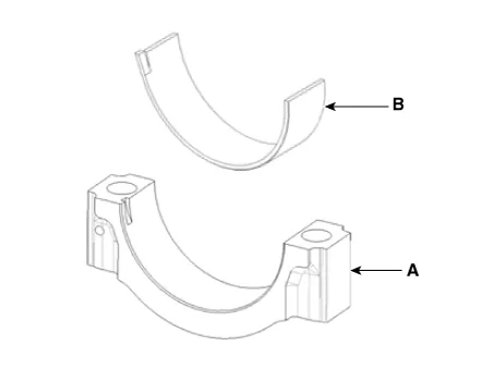
Check the connecting rod bearing oil clearance.
|
|||||||||||||||||||||||||||||||||||||||||||||||||||||||||||||||||||||||||||||||||||||||||||||||||||||||||||||||||


| 3. |
Check the connecting rod.
|

| 1. |
Clean piston
|

| 2. |
Check the piston - to - cylinder clearance by calculating the difference
between the cylinder bore inner diameter and the piston outer diameter.
|
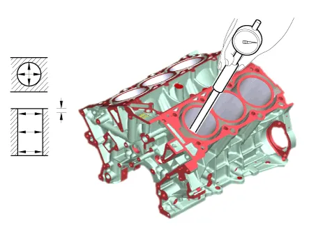
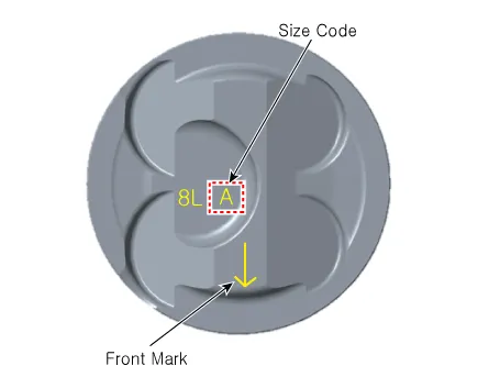
| 3. |
Select piston by the cylinder bore class.
|
| 1. |
Inspect the piston ring side clearance.
Using a feeler gauge, measure the clearance between new piston ring
and the wall of the ring groove.
If the clearance is greater than maximum, replace the piston.
|
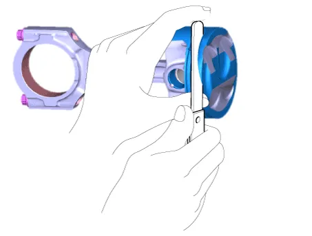
| 2. |
Inspect piston ring end gap.
To measure the piston ring end gap, insert a piston ring into the cylinder
bore. Position the ring at right angles to the cylinder wall by gently
pressing it down with a piston. Measure the gap with a feeler gauge.
If the gap exceeds the service limit, replace the piston ring. If the
gap is too large, recheck the cylinder bore diameter against the wear
limits. If the bore is over the service limit, the cylinder block must
be replaced.
|

| 1. |
Measure the diameter of the piston pin.
|
| 2. |
Measure the piston pin-to-piston clearance.
|
| 3. |
Check the difference between the piston pin diameter and the connecting
rod small end diameter.
|
| Reassembly |
|

| 1. |
Assemble the piston and the connecting rod.
|
| 2. |
Install the piston rings.
|
| 3. |
Install the connecting rod bearings.
|

| 4. |
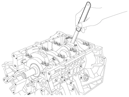
Attach the piston and connecting rod assemblies on the cylinder block.
|


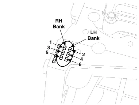
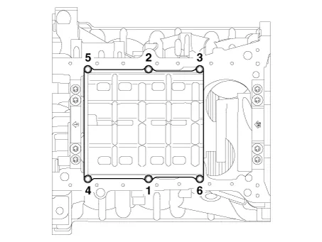
| 5. |
Install the baffle plate.
Install and uniformly tighten the baffle plate bolts, in several passes,
in the sequence shown.
|
| 6. |
Assemble the remaining parts in the reverse order of disassembly.
|
Repair procedures Replacement • Be careful not to damage the parts located under the vehicle (floor under cover, fuel filter, fuel tank and canister) when raising the vehicle using the lift.
Repair procedures Disassembly • Be careful not to damage the parts located under the vehicle (floor under cover, fuel filter, fuel tank and canister) when raising the vehicle using the lift.
Other information:
Hyundai Palisade (LX2) 2020-2026 Service Manual: Smart Cruise Control (SCC) Switch
Components and components location Components 1. Remote control switch (Audio swtich) 2. Remote control switch (Cruise control switch) Schematic diagrams Circuit Diagram Trip + SCC Repair procedures Removal 1.
Hyundai Palisade (LX2) 2020-2026 Service Manual: Description and operation
Description Rear view camera will activate when the backup light is ON with the ignition switch ON and the shift lever in the R position. This system is a supplemental system that shows behind the vehicle through the AV monitor or the ECM (Reverse Display Room Mirror) mirror while backing-up.
Categories
- Manuals Home
- Hyundai Palisade Owners Manual
- Hyundai Palisade Service Manual
- Engine Mechanical System
- Body (Interior and Exterior)
- Scheduled maintenance services
- New on site
- Most important about car
