Hyundai Palisade (LX2): Front View Camera System / Front View Camera Unit
Hyundai Palisade (LX2) 2020-2026 Service Manual / Advanced Driver Assistance System (ADAS) / Front View Camera System / Front View Camera Unit
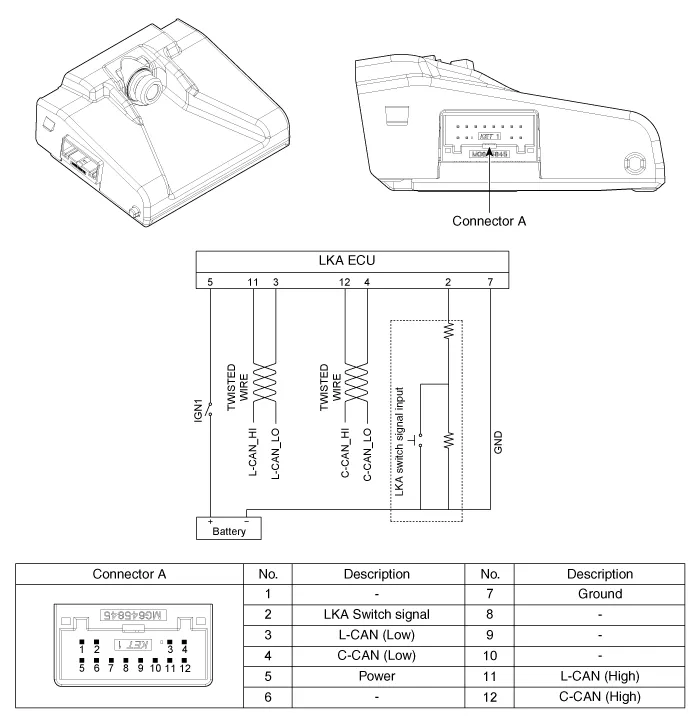
Schematic diagrams
| Circuit Diagram |
Repair procedures
| Removal |
| 1. |
Disconnect the negative (-) battery terminal.
|
| 2. |
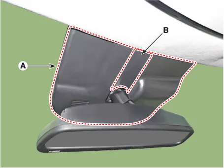
Remove the inside rear view mirror cover (A) and rain sensor cover (B).
|
| 3. |
Disconnect the front view camera unit connector (A).
|
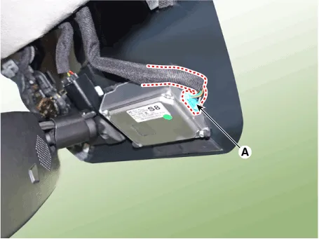
| 4. |
Separate the fixed points (A) of coupler, remove the front view camera
(B).
|

| Installation |
|

| 1. |
Install in the reverse order of removal.
|
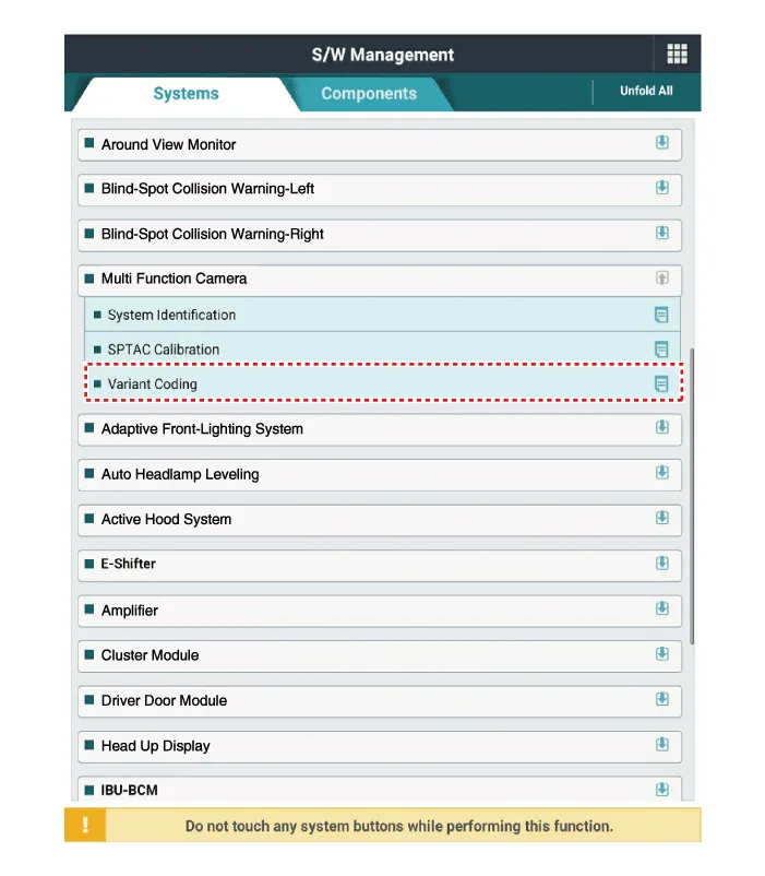
| 2. |
When if replacing the front view camera with a new one, perform the
"Variant Coding" procedure by using the Diagnostic Tools.
|
| 3. |
Perform the front view camera unit calibration.
(Refer to Repair procedures - "Service Point Target Auto Calibration
(SPTAC)")
|
Variant Coding When you need variant coding: – Replace Front View Camera with a new one ※ EOL Variant Coding and calibration required for new replacement Front View Camera Variant Coding Front view camera variant coding makes it possible to operate functions for each vehicle type.
Other information:
Hyundai Palisade (LX2) 2020-2026 Service Manual: Description and operation
Hyundai Palisade (LX2) 2020-2026 Service Manual: Repair procedures
Removal SVM Rear Camera • In case of bad quality or poor focus, be sure to check the camera lense surface condition and foreign materials.
Categories
- Manuals Home
- Hyundai Palisade Owners Manual
- Hyundai Palisade Service Manual
- General Tightening Torque Table
- Electrochromatic Mirror (ECM) with homelink system
- Maintenance
- New on site
- Most important about car

Copyright © 2026 www.hpalisadelx.com - 0.0163