Hyundai Palisade (LX2): Cylinder Block / Cylinder Block
Hyundai Palisade (LX2) 2020-2026 Service Manual / Engine Mechanical System / Cylinder Block / Cylinder Block
Repair procedures
| Disassembly |
|

|

|

| 1. |
Remove the engine assembly from the vehicle.
(Refer to Engine and Transaxle Assembly - "Engine And Transaxle Assembly")
|
| 2. |
Remove the transaxle assembly from the engine assembly.
(Refer to Automatic Transaxle System - "Automatic Transaxle")
|
| 3. |
Remove the drive plate and adapter plate.
(Refer to Cylinder Block - "Drive Plate")
|
| 4. |
Remove the rear oil seal case.
(Refer to Cylinder Block - "Rear Oil Seal")
|
| 5. |
Install the engine assembly to engine stand for disassembly.
|
| 6. |
Remove the surge tank.
(Refer to Intake and Exhaust System - "Surge Tank")
|
| 7. |
Remove the intake manifold.
(Refer to Intake and Exhaust System - "Intake Manifold")
|
| 8. |
Remove the exhaust manifold.
(Refer to Intake and Exhaust System - "Exhaust Manifold")
|
| 9. |
Remove the timing chain.
(Refer to Timing System - "Timing Chain")
|
| 10. |
Remove the water temperature control assembly.
(Refer to Cooling System - "Water Temperature Control Assembly")
|
| 11. |
Remove the cylinder head assembly.
(Refer to Cylinder Head Assembly - "Cylinder Head")
|
| 12. |
Remove the lower oil pan and upper oil pan.
(Refer to Lubrication System - "Oil Pan")
|
| 13. |
Remove the oil pump.
(Refer to Lubrication System - "Oil Pump")
|
| 14. |
Remove the oil filter body.
(Refer to Lubrication System - "Oil filter body")
|
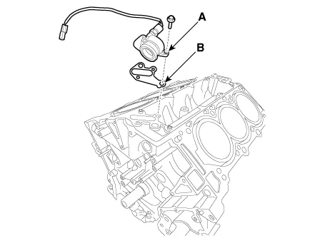
| 15. |
Remove the oil cover (A) and gasket (B).
|
| 16. |
Remove the water jacket separator.
(Refer to Cylinder Block - "Water Jacket Separator")
|
| 17. |
Remove the knock sensor.
(Refer to Engine Control / Fuel System - "Knock Sensor")
|
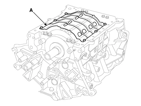
| 18. |
Remove the baffle plate (A).
|
| 19. |
Check the connecting rod end play.
(Refer to Cylinder Block - "Piston and Connecting Rod")
|
| 20. |
Check the connecting rod cap oil clearance.
(Refer to Cylinder Block - "Piston and Connecting Rod")
|
| 21. |
Remove the piston and connecting rod assemblies.
(Refer to Cylinder Block - "Piston and Connecting Rod")
|
| 22. |
Remove the crankshaft main bearing cap and check oil clearance.
(Refer to Cylinder Block - "Crankshaft")
|
| 23. |
Check the crankshaft end play.
(Refer to Cylinder Block - "Crankshaft")
|
| 24. |
Remove the crankshaft.
(Refer to Cylinder Block - "Crankshaft")
|
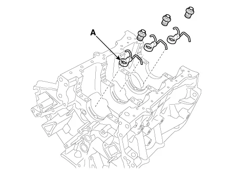
| 25. |
Remove the oil jets (A).
|
| Inspection |
Cylinder Block
| 1. |
Remove the gasket material.
Using a gasket scraper, remove all the gasket material from the top
surface of the cylinder block.
|
| 2. |
Clean the cylinder block.
Using a soft brush and solvent, thoroughly clean the cylinder block.
|
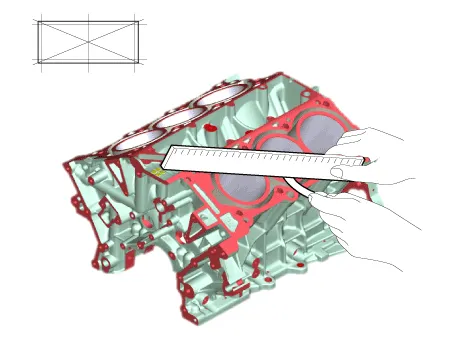
| 3. |
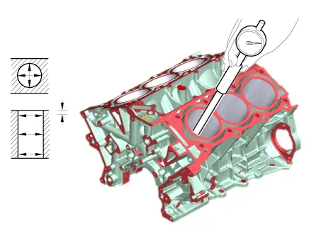
Inspect the top surface of the cylinder block for flatness.
Using a precision straight edge and feeler gauge, measure the warpage
of the surface contacting with the cylinder head gasket.
|
| 4. |
Inspect cylinder bore diameter.
Visually check the cylinder for vertical scratches.
If deep scratches are present, replace the cylinder block.
|
| 5. |
Inspect cylinder bore diameter
Using a cylinder bore gauge, measure the cylinder bore diameter in the
direction of the thrust and axial.
|
| 6. |
Check the cylinder bore size code on the cylinder block.
|
| Reassembly |
| 1. |
Install the oil jets (A).
|

| 2. |
Install the crankshaft.
(Refer to Cylinder Block - "Crankshaft")
|
| 3. |
Install the crankshaft main bearing cap and check oil clearance.
(Refer to Cylinder Block - "Crankshaft")
|
| 4. |
Check the crankshaft end play.
(Refer to Cylinder Block - "Crankshaft")
|
| 5. |
Install the piston and connecting rod assemblies.
(Refer to Cylinder Block - "Piston and Connecting Rod")
|
| 6. |
Check the connecting rod end play.
(Refer to Cylinder Block - Piston and Connecting Rod")
|
| 7. |
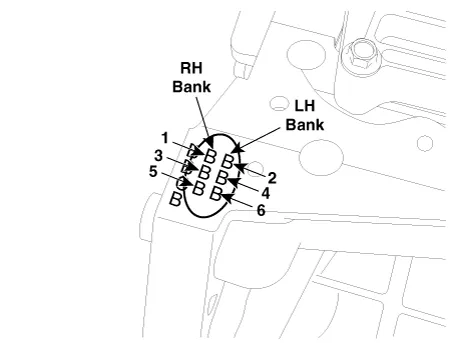
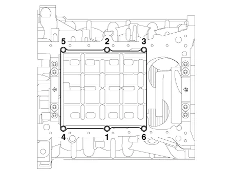
Install the baffle plate.
Install and uniformly tighten the baffle plate bolts, in several passes,
in the sequence shown.
|
| 8. |
Install the knock sensor.
(Refer to Engine Control / Fuel System - "Knock Sensor")
|
| 9. |
Install the water jacket separator.
(Refer to Cylinder Block - "Water Jacket Separator")
|
| 10. |
Install the oil cover (A) and gasket (B).
|

| 11. |
Assemble the remaining parts in the reverse order of disassembly.
|

Repair procedures Disassembly • Be careful not to damage the parts located under the vehicle (floor under cover, fuel filter, fuel tank and canister) when raising the vehicle using the lift.
Other information:
Hyundai Palisade (LX2) 2020-2026 Service Manual: Components and positions
Hyundai Palisade (LX2) 2020-2026 Service Manual: Troubleshooting
Trouble Symptom Charts Trouble Symptom 1 Trouble Symptom 2 Trouble symptom Probable cause Remedy The set vehicle speed varies greatly upward or downward "Surging" (repeated alternating acceleration and deceleration) occurs after set
Categories
- Manuals Home
- Hyundai Palisade Owners Manual
- Hyundai Palisade Service Manual
- Convenient Features of Your Vehicle
- Scheduled maintenance services
- Resetting the Driver's Seat Memory System
- New on site
- Most important about car

Copyright © 2026 www.hpalisadelx.com - 0.0196