Hyundai Palisade: Crash Pad / Components and components location

Hyundai Palisade (LX2) 2020-2025 Service Manual / Body (Interior and Exterior) / Crash Pad / Components and components location

Components (1)

Hyundai Palisade. Components and components location

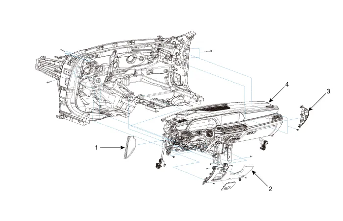
1. Crash pad side cover [LH]
2. Crash pad lower panel
3. Crash pad side cover [RH]
4. Crash pad assembly

Componets (2)

Hyundai Palisade. Components and components location

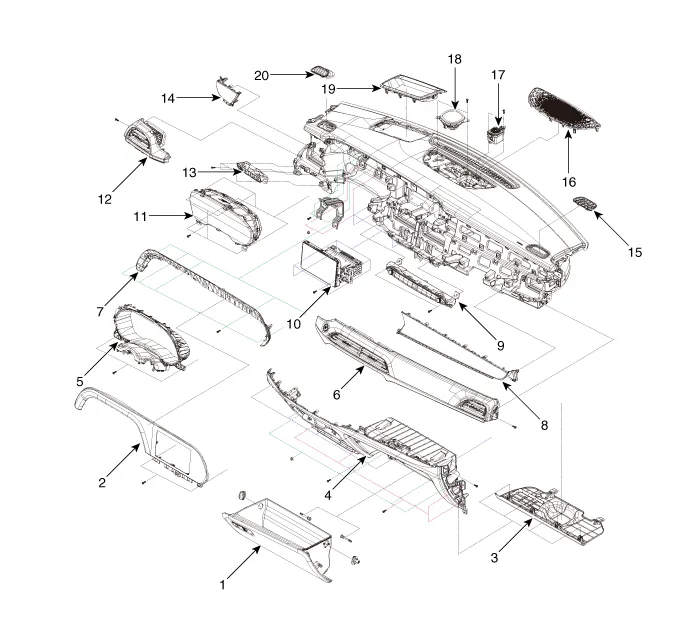
1. Glove box
2. Front center fascia panel
3. Crash pad under cover
4. Crash pad center panel
5. Cluster fascia panel
6. Crash pad center garnish
7. Rear center fascia panel
8. Crash pad garnish [RH]
9. Audio keyborad assembly
10. AVN Head unit
11. Cluster assembly
12. Side airvent duct assembly [LH]
13. Crash pad lower switch assembly
14. Crash pad garnish [LH]
15. Side defroster nozzle assembly [RH]
16. Center speaker grill assembly
17. Cluster speaker assembly
18. Front center speaker assembly
19. Head up display cover
20. Side defroster nozzle assembly [LH]

    Crash Pad

    ..

    Cluster Fascia Panel

    Components and components location Component Location 1. Cluster fascia panel Repair procedures Replacement    • When removing with a flat-tip screwdriver or remover, wrap protective tape around the tools to prevent damage to components...

    Other information:

    Hyundai Palisade (LX2) 2020-2025 Service Manual: Engine Control Module (ECM)


    Schematic diagrams ECM Terminal and Input / Output Signal ECM Terminal Function Connector [A] Pin No Description Connected to 1 Ignition Coil (Cylinder #4) control output Ignition Coil (Cylinder #4) 2 Injector (Cylinder #3) [High] control output Injector (Cylinder #3) 3 Injector (Cylinder #5) [High] control output Injector (Cylinder #5) 4 Injector (Cylinder #1) [High] control output Injector (Cylinder #1) 5 Camshaft Position Sensor (CMPS) [Bank 2 / Exhaust] signal input Camshaft Position Sensor (CMPS) [Bank 2 / Exhaust] 6 Camshaft Position Sensor (CMPS) [Bank 2 / Intake] signal input Camshaft Position Sensor (CMPS) [Bank 2 / Intake] 7 Throttle Position Sensor (TPS) 2 signal input Throttle Position Sensor (TPS) 2 8 -   9 Rail Pressure Sensor (RPS) signal input Rail Pressure Sensor (RPS) 10 CVVT Oil Temperature Sensor (OTS) signal input CVVT Oil Temperature Sensor (OTS) 11 -   12 -   13 Sensor power (+5V) CVVT Oil Temperature Sensor (OTS) Manifold Absolute Pressure Sensor (MAPS) 14 -   15 -   16 -   17 -   18 -   19 ETC Motor [-] control output ETC Motor 20 Heated Oxygen Sensor (HO2S) [Bank 1 / Sensor 1] Heater control output Heated Oxygen Sensor (HO2S) [Bank 1 / Sensor 1] 21 Heated Oxygen Sensor (HO2S) [Bank 2 / Sensor 1] Heater control output Heated Oxygen Sensor (HO2S) [Bank 2 / Sensor 1] 22 Ignition Coil (Cylinder #5) control output Ignition Coil (Cylinder #5 23 Injector (Cylinder #6) [High] control output Injector (Cylinder #6) 24 Injector (Cylinder #2) [High] control output Injector (Cylinder #2) 25 Injector (Cylinder #4) [High] control output Injector (Cylinder #4) 26 Camshaft Position Sensor (CMPS) [Bank 1 / Exhaust] signal input Camshaft Position Sensor (CMPS) [Bank 1 / Exhaust] 27 Camshaft Position Sensor (CMPS) [Bank 1 / Intake] signal input Camshaft Position Sensor (CMPS) [Bank 1 / Intake] 28 Intake Air Temperature Sensor (IATS) signal input Intake Air Temperature Sensor (IATS) 29 Manifold Absolute Pressure Sensor (MAPS) signal input Manifold Absolute Pressure Sensor (MAPS) 30 -   31 -   32 -   33 -   34 Sensor power (+5V) Camshaft Position Sensor (CMPS) [Bank 1 / Exhaust] Camshaft Position Sensor (CMPS) [Bank 2 / Intake] 35 -   36 Sensor power (+5V) Camshaft Position Sensor (CMPS) [Bank 1 / Intake] Camshaft Position Sensor (CMPS) [Bank 2 / Exhaust] 37 -   38 Purge Control Solenoid Valve (PCSV) control output Purge Control Solenoid Valve (PCSV) 39 -   40 ETC Motor [+] control output ETC Motor 41 -   42 -   43 Ignition Coil (Cylinder #1) control output Ignition Coil (Cylinder #1) 44 Injector (Cylinder #6) [Low] control output Injector (Cylinder #6) 45 Injector (Cylinder #3) [Low] control output Injector (Cylinder #3) 46 Injector (Cylinder #2) [Low] control output Injector (Cylinder #2) 47 Sensor ground Camshaft Position Sensor (CMPS) [Bank 1 / Exhaust] Camshaft Position Sensor (CMPS) [Bank 2 / Intake] 48 Sensor ground Manifold Absolute Pressure Sensor (MAPS) Oil Pressure Sensor (OPS) 49 Sensor ground Camshaft Position Sensor (CMPS) [Bank 1 / Intake] Camshaft Position Sensor (CMPS) [Bank 2 / Exhaust] 50 -   51 -   52 -   53 -   54 Engine Coolant Temperature Sensor (ECTS) signal input Engine Coolant Temperature Sensor (ECTS) 55 Sensor Shield Crankshaft Position Sensor (CKPS) Knock Sensor (KS) #1 [Bank 1] Knock Sensor (KS) #2 [Bank 2] 56 Sensor power (+5V) Rail Pressure Sensor (RPS) 57 -   58 Sensor ground Engine Coolant Temperature Sensor (ECTS) Rail Pressure Sensor (RPS) 59 Sensor ground Throttle Position Sensor (TPS) 1 Throttle Position Sensor (TPS) 2 60 Variable Intake Solenoid (VIS) Valve 1 control output Variable Intake Solenoid (VIS) Valve 1 61 Variable Intake Solenoid (VIS) Valve 2 control output Variable Intake Solenoid (VIS) Valve 2 62 -   63 -   64 Ignition Coil (Cylinder #2) control output Ignition Coil (Cylinder #2) 65 Injector (Cylinder #1) [Low] control output Injector (Cylinder #1) 66 Injector (Cylinder #4) [Low] control output Injector (Cylinder #4) 67 Injector (Cylinder #5) [Low] control output Injector (Cylinder #5) 68 Crankshaft Position Sensor (CKPS) [High] signal input Crankshaft Position Sensor (CKPS) 69 Crankshaft Position Sensor (CKPS) [Low] signal input Crankshaft Position Sensor (CKPS) 70 -   71 -   72 Oil pressure switch signal input Oil Pressure Sensor (OPS) 73 -   74 -   75 Throttle Position Sensor (TPS) 1 signal input Throttle Position Sensor (TPS) 1 76 Knock Sensor (KS) [Bank 1] [Low] signal input Knock Sensor (KS) [Bank 1] 77 Knock Sensor (KS) [Bank 2] [Low] signal input Knock Sensor (KS) [Bank 2] 78 Sensor ground Heated Oxygen Sensor (HO2S) [Bank 2 / Sensor 2] 79 Rc/Rp (Pump Cell Voltage) Heated Oxygen Sensor (HO2S) [Bank 2 / Sensor 1] 80 VS+ (NERNST Cell Voltage) Heated Oxygen Sensor (HO2S) [Bank 2 / Sensor 1] 81 Heated Oxygen Sensor (HO2S) [Bank 2 / Sensor 2] signal input Heated Oxygen Sensor (HO2S) [Bank 2 / Sensor 2] 82 VS+ (NERNST Cell Voltage) Heated Oxygen Sensor (HO2S) [Bank 1 / Sensor 1] 83 Rc (Compensative Resistance) Heated Oxygen Sensor (HO2S) [Bank 1 / Sensor 1] 84 Oil Pressure Solenoid Valve control output Oil Pressure Solenoid Valve 85 Ignition Coil (Cylinder #6) control output Ignition Coil (Cylinder #6) 86 Ignition Coil (Cylinder #3) control output Ignition Coil (Cylinder #3) 87 Fuel Pressure Control Valve (FPCV) [High] control output Fuel Pressure Control Valve (FPCV) 88 Fuel Pressure Control Valve (FPCV) [Low] control output Fuel Pressure Control Valve (FPCV) 89 Heated Oxygen Sensor (HO2S) [Bank 2 / Sensor 2] Heater control output Heated Oxygen Sensor (HO2S) [Bank 2 / Sensor 2] 90 Heated Oxygen Sensor (HO2S) [Bank 1 / Sensor 2] Heater control output Heated Oxygen Sensor (HO2S) [Bank 1 / Sensor 2] 91 CVVT Oil Control Valve (OCV) [Bank 2 / Exhaust] control output CVVT Oil Control Valve (OCV) [Bank 2 / Exhaust] 92 CVVT Oil Control Valve (OCV) [Bank 1 / Exhaust] control output CVVT Oil Control Valve (OCV) [Bank 1 / Exhaust] 93 Variable Force Solenoid (VFS) [Bank 2 / Intake] control output Variable Force Solenoid (VFS) [Bank 2 / Intake] 94 Variable Force Solenoid (VFS) [Bank 1 / Intake] control output Variable Force Solenoid (VFS) [Bank 1 / Intake] 95 -   96 Sensor power (+5V) Throttle Position Sensor (TPS) 1 Throttle Position Sensor (TPS) 2 97 Knock Sensor (KS) [Bank 1] [High] signal input Knock Sensor (KS) [Bank 1] 98 Knock Sensor (KS) [Bank 2] [High] signal input Knock Sensor (KS) [Bank 2] 99 Sensor ground Heated Oxygen Sensor (HO2S) [Bank 1 / Sensor 2] 100 -   101 Rc (Compensative Resistance) Heated Oxygen Sensor (HO2S) [Bank 2 / Sensor 1] 102 VS-/IP- (Common ground) Heated Oxygen Sensor (HO2S) [Bank 2 / Sensor 1] 103 Heated Oxygen Sensor (HO2S) [Bank 1 / Sensor 2] signal input Heated Oxygen Sensor (HO2S) [Bank 1 / Sensor 2] 104 VS-/IP- (Common ground) Heated Oxygen Sensor (HO2S) [Bank 1 / Sensor 1] 105 Rc/Rp (Pump Cell Voltage) Heated Oxygen Sensor (HO2S) [Bank 1 / Sensor 1] Connector [K] Pin No Description Connected to 1 ECM ground Chassis ground 2 ECM ground Chassis ground 3 Battery power (B+) Main Relay 4 ECM ground Chassis ground 5 Battery power (B+) Main Relay 6 Battery power (B+) Main Relay 7 -   8 -   9 -   10 -   11 -   12 -   13 Sensor ground A/C Pressure Transducer (APT) 14 Immobilizer communication line Immobilizer Control Module 15 Fuel Level Sender (FLS) signal input [Fuel pump] Fuel Level Sender (FLS) 16 -   17 -   18 -   19 -   20 Sensor power (+5V) Accelerator Position Sensor (APS) 1 21 Main Relay control output Main Relay 22 -   23 -   24 -   25 -   26 -   27 -   28 Accelerator Position Sensor (APS) 2 signal input Accelerator Position Sensor (APS) 2 29 -   30 -   31 -   32 Fuel Level Sender (FLS) signal input [Sub Fuel Sender] Sub Fuel Level Sender 33 Fuel Pump Relay control output Fuel Pump Relay 34 -   35 Sensor power (+5V) A/C Pressure Transducer (APT) 36 Sensor power (+5V) Accelerator Position Sensor (APS) 2 37 -   38 Vehicle speed signal input VDC control module 39 -   40 -   41 Start signal input Start Relay 42 -   43 -   44 -   45 -   46 -   47 Sensor ground Accelerator Position Sensor (APS) 2 48 -   49 Brake Switch [Test] signal input Brake Switch 50 -   51 -   52 Sensor ground Accelerator Position Sensor (APS) 1 53 -   54 -   55 -   56 -   57 -   58 -   59 -   60 P-CAN [Low] Other control module, Data Link Connector (DLC), Multi-Purpose Check Connector 61 -   62 -   63 -   64 A/C Pressure Transducer (APT) signal input A/C Pressure Transducer (APT) 65 -   66 -   67 -   68 -   69 LIN (Local Interconnect Network) Serial Bus Line Battery Sensor 70 -   71 Cooling Fan Relay control output Cooling Fan Relay 72 Engine speed signal output Integrated Body Control Unit (IBU) 73 -   74 -   75 -   76 -   77 P-CAN [High] Other control module, Data Link Connector (DLC), Multi-Purpose Check Connector 78 -   79 Start Relay control output Start Relay 80 -   81 -   82 Accelerator Position Sensor (APS) 1 signal input Accelerator Position Sensor (APS) 1 83 Brake Switch [Light] signal input Brake Switch 84 -   85 -   86 -   87 -   88 -   89 -   90 -   91 -   ECM Terminal Input/ Output signal Connector [A] Pin No  Description Condition Type Level 1 Ignition Coil (Cylinder #4) control output Idle Pulse Vpeak = 400V Frequency : 0 - 58...

    Hyundai Palisade (LX2) 2020-2025 Owner's Manual: Normal Maintenance Schedule (3.8 GDI)


    I : Inspect and if necessary, adjust, correct, clean or replace. R : Replace or change. *1 : The drive belt should be replaced when cracks occur or tension is reduced. *2 : If TOP TIER Detergent Gasoline is not available, one bottle of additive is recommended...

    Categories

    Battery replacement

    Hyundai Palisade. Battery replacement

    If the remote key is not working properly, try replacing the battery with a new one.

    Battery Type: CR2032

    To replace the battery:

    read more


    Copyright © 2025 www.hpalisadelx.com