Hyundai Palisade (LX2): Engine Control System / Engine Control Module (ECM)
Schematic diagrams
| ECM Terminal and Input / Output Signal |
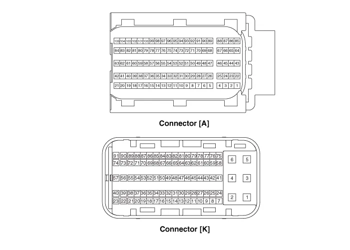
| ECM Terminal Function |
|
Pin No |
Description |
Connected to |
|
1 |
Ignition Coil (Cylinder #4) control output |
Ignition Coil (Cylinder #4) |
|
2 |
Injector (Cylinder #3) [High] control output |
Injector (Cylinder #3) |
|
3 |
Injector (Cylinder #5) [High] control output |
Injector (Cylinder #5) |
|
4 |
Injector (Cylinder #1) [High] control output |
Injector (Cylinder #1) |
|
5 |
Camshaft Position Sensor (CMPS) [Bank 2 / Exhaust] signal input |
Camshaft Position Sensor (CMPS) [Bank 2 / Exhaust] |
|
6 |
Camshaft Position Sensor (CMPS) [Bank 2 / Intake] signal input |
Camshaft Position Sensor (CMPS) [Bank 2 / Intake] |
|
7 |
Throttle Position Sensor (TPS) 2 signal input |
Throttle Position Sensor (TPS) 2 |
|
8 |
- |
  |
|
9 |
Rail Pressure Sensor (RPS) signal input |
Rail Pressure Sensor (RPS) |
|
10 |
CVVT Oil Temperature Sensor (OTS) signal input |
CVVT Oil Temperature Sensor (OTS) |
|
11 |
- |
  |
|
12 |
- |
  |
|
13 |
Sensor power (+5V) |
CVVT Oil Temperature Sensor (OTS) |
|
Manifold Absolute Pressure Sensor (MAPS) |
||
|
14 |
- |
  |
|
15 |
- |
  |
|
16 |
- |
  |
|
17 |
- |
  |
|
18 |
- |
  |
|
19 |
ETC Motor [-] control output |
ETC Motor |
|
20 |
Heated Oxygen Sensor (HO2S) [Bank 1 / Sensor 1] Heater control output |
Heated Oxygen Sensor (HO2S) [Bank 1 / Sensor 1] |
|
21 |
Heated Oxygen Sensor (HO2S) [Bank 2 / Sensor 1] Heater control output |
Heated Oxygen Sensor (HO2S) [Bank 2 / Sensor 1] |
|
22 |
Ignition Coil (Cylinder #5) control output |
Ignition Coil (Cylinder #5 |
|
23 |
Injector (Cylinder #6) [High] control output |
Injector (Cylinder #6) |
|
24 |
Injector (Cylinder #2) [High] control output |
Injector (Cylinder #2) |
|
25 |
Injector (Cylinder #4) [High] control output |
Injector (Cylinder #4) |
|
26 |
Camshaft Position Sensor (CMPS) [Bank 1 / Exhaust] signal input |
Camshaft Position Sensor (CMPS) [Bank 1 / Exhaust] |
|
27 |
Camshaft Position Sensor (CMPS) [Bank 1 / Intake] signal input |
Camshaft Position Sensor (CMPS) [Bank 1 / Intake] |
|
28 |
Intake Air Temperature Sensor (IATS) signal input |
Intake Air Temperature Sensor (IATS) |
|
29 |
Manifold Absolute Pressure Sensor (MAPS) signal input |
Manifold Absolute Pressure Sensor (MAPS) |
|
30 |
- |
  |
|
31 |
- |
  |
|
32 |
- |
  |
|
33 |
- |
  |
|
34 |
Sensor power (+5V) |
Camshaft Position Sensor (CMPS) [Bank 1 / Exhaust] |
|
Camshaft Position Sensor (CMPS) [Bank 2 / Intake] |
||
|
35 |
- |
  |
|
36 |
Sensor power (+5V) |
Camshaft Position Sensor (CMPS) [Bank 1 / Intake] |
|
Camshaft Position Sensor (CMPS) [Bank 2 / Exhaust] |
||
|
37 |
- |
  |
|
38 |
Purge Control Solenoid Valve (PCSV) control output |
Purge Control Solenoid Valve (PCSV) |
|
39 |
- |
  |
|
40 |
ETC Motor [+] control output |
ETC Motor |
|
41 |
- |
  |
|
42 |
- |
  |
|
43 |
Ignition Coil (Cylinder #1) control output |
Ignition Coil (Cylinder #1) |
|
44 |
Injector (Cylinder #6) [Low] control output |
Injector (Cylinder #6) |
|
45 |
Injector (Cylinder #3) [Low] control output |
Injector (Cylinder #3) |
|
46 |
Injector (Cylinder #2) [Low] control output |
Injector (Cylinder #2) |
|
47 |
Sensor ground |
Camshaft Position Sensor (CMPS) [Bank 1 / Exhaust] |
|
Camshaft Position Sensor (CMPS) [Bank 2 / Intake] |
||
|
48 |
Sensor ground |
Manifold Absolute Pressure Sensor (MAPS) |
|
Oil Pressure Sensor (OPS) |
||
|
49 |
Sensor ground |
Camshaft Position Sensor (CMPS) [Bank 1 / Intake] |
|
Camshaft Position Sensor (CMPS) [Bank 2 / Exhaust] |
||
|
50 |
- |
  |
|
51 |
- |
  |
|
52 |
- |
  |
|
53 |
- |
  |
|
54 |
Engine Coolant Temperature Sensor (ECTS) signal input |
Engine Coolant Temperature Sensor (ECTS) |
|
55 |
Sensor Shield |
Crankshaft Position Sensor (CKPS) |
|
Knock Sensor (KS) #1 [Bank 1] |
||
|
Knock Sensor (KS) #2 [Bank 2] |
||
|
56 |
Sensor power (+5V) |
Rail Pressure Sensor (RPS) |
|
57 |
- |
  |
|
58 |
Sensor ground |
Engine Coolant Temperature Sensor (ECTS) |
|
Rail Pressure Sensor (RPS) |
||
|
59 |
Sensor ground |
Throttle Position Sensor (TPS) 1 |
|
Throttle Position Sensor (TPS) 2 |
||
|
60 |
Variable Intake Solenoid (VIS) Valve 1 control output |
Variable Intake Solenoid (VIS) Valve 1 |
|
61 |
Variable Intake Solenoid (VIS) Valve 2 control output |
Variable Intake Solenoid (VIS) Valve 2 |
|
62 |
- |
  |
|
63 |
- |
  |
|
64 |
Ignition Coil (Cylinder #2) control output |
Ignition Coil (Cylinder #2) |
|
65 |
Injector (Cylinder #1) [Low] control output |
Injector (Cylinder #1) |
|
66 |
Injector (Cylinder #4) [Low] control output |
Injector (Cylinder #4) |
|
67 |
Injector (Cylinder #5) [Low] control output |
Injector (Cylinder #5) |
|
68 |
Crankshaft Position Sensor (CKPS) [High] signal input |
Crankshaft Position Sensor (CKPS) |
|
69 |
Crankshaft Position Sensor (CKPS) [Low] signal input |
Crankshaft Position Sensor (CKPS) |
|
70 |
- |
  |
|
71 |
- |
  |
|
72 |
Oil pressure switch signal input |
Oil Pressure Sensor (OPS) |
|
73 |
- |
  |
|
74 |
- |
  |
|
75 |
Throttle Position Sensor (TPS) 1 signal input |
Throttle Position Sensor (TPS) 1 |
|
76 |
Knock Sensor (KS) [Bank 1] [Low] signal input |
Knock Sensor (KS) [Bank 1] |
|
77 |
Knock Sensor (KS) [Bank 2] [Low] signal input |
Knock Sensor (KS) [Bank 2] |
|
78 |
Sensor ground |
Heated Oxygen Sensor (HO2S) [Bank 2 / Sensor 2] |
|
79 |
Rc/Rp (Pump Cell Voltage) |
Heated Oxygen Sensor (HO2S) [Bank 2 / Sensor 1] |
|
80 |
VS+ (NERNST Cell Voltage) |
Heated Oxygen Sensor (HO2S) [Bank 2 / Sensor 1] |
|
81 |
Heated Oxygen Sensor (HO2S) [Bank 2 / Sensor 2] signal input |
Heated Oxygen Sensor (HO2S) [Bank 2 / Sensor 2] |
|
82 |
VS+ (NERNST Cell Voltage) |
Heated Oxygen Sensor (HO2S) [Bank 1 / Sensor 1] |
|
83 |
Rc (Compensative Resistance) |
Heated Oxygen Sensor (HO2S) [Bank 1 / Sensor 1] |
|
84 |
Oil Pressure Solenoid Valve control output |
Oil Pressure Solenoid Valve |
|
85 |
Ignition Coil (Cylinder #6) control output |
Ignition Coil (Cylinder #6) |
|
86 |
Ignition Coil (Cylinder #3) control output |
Ignition Coil (Cylinder #3) |
|
87 |
Fuel Pressure Control Valve (FPCV) [High] control output |
Fuel Pressure Control Valve (FPCV) |
|
88 |
Fuel Pressure Control Valve (FPCV) [Low] control output |
Fuel Pressure Control Valve (FPCV) |
|
89 |
Heated Oxygen Sensor (HO2S) [Bank 2 / Sensor 2] Heater control output |
Heated Oxygen Sensor (HO2S) [Bank 2 / Sensor 2] |
|
90 |
Heated Oxygen Sensor (HO2S) [Bank 1 / Sensor 2] Heater control output |
Heated Oxygen Sensor (HO2S) [Bank 1 / Sensor 2] |
|
91 |
CVVT Oil Control Valve (OCV) [Bank 2 / Exhaust] control output |
CVVT Oil Control Valve (OCV) [Bank 2 / Exhaust] |
|
92 |
CVVT Oil Control Valve (OCV) [Bank 1 / Exhaust] control output |
CVVT Oil Control Valve (OCV) [Bank 1 / Exhaust] |
|
93 |
Variable Force Solenoid (VFS) [Bank 2 / Intake] control output |
Variable Force Solenoid (VFS) [Bank 2 / Intake] |
|
94 |
Variable Force Solenoid (VFS) [Bank 1 / Intake] control output |
Variable Force Solenoid (VFS) [Bank 1 / Intake] |
|
95 |
- |
  |
|
96 |
Sensor power (+5V) |
Throttle Position Sensor (TPS) 1 |
|
Throttle Position Sensor (TPS) 2 |
||
|
97 |
Knock Sensor (KS) [Bank 1] [High] signal input |
Knock Sensor (KS) [Bank 1] |
|
98 |
Knock Sensor (KS) [Bank 2] [High] signal input |
Knock Sensor (KS) [Bank 2] |
|
99 |
Sensor ground |
Heated Oxygen Sensor (HO2S) [Bank 1 / Sensor 2] |
|
100 |
- |
  |
|
101 |
Rc (Compensative Resistance) |
Heated Oxygen Sensor (HO2S) [Bank 2 / Sensor 1] |
|
102 |
VS-/IP- (Common ground) |
Heated Oxygen Sensor (HO2S) [Bank 2 / Sensor 1] |
|
103 |
Heated Oxygen Sensor (HO2S) [Bank 1 / Sensor 2] signal input |
Heated Oxygen Sensor (HO2S) [Bank 1 / Sensor 2] |
|
104 |
VS-/IP- (Common ground) |
Heated Oxygen Sensor (HO2S) [Bank 1 / Sensor 1] |
|
105 |
Rc/Rp (Pump Cell Voltage) |
Heated Oxygen Sensor (HO2S) [Bank 1 / Sensor 1] |
|
Pin No |
Description |
Connected to |
|
1 |
ECM ground |
Chassis ground |
|
2 |
ECM ground |
Chassis ground |
|
3 |
Battery power (B+) |
Main Relay |
|
4 |
ECM ground |
Chassis ground |
|
5 |
Battery power (B+) |
Main Relay |
|
6 |
Battery power (B+) |
Main Relay |
|
7 |
- |
  |
|
8 |
- |
  |
|
9 |
- |
  |
|
10 |
- |
  |
|
11 |
- |
  |
|
12 |
- |
  |
|
13 |
Sensor ground |
A/C Pressure Transducer (APT) |
|
14 |
Immobilizer communication line |
Immobilizer Control Module |
|
15 |
Fuel Level Sender (FLS) signal input [Fuel pump] |
Fuel Level Sender (FLS) |
|
16 |
- |
  |
|
17 |
- |
  |
|
18 |
- |
  |
|
19 |
- |
  |
|
20 |
Sensor power (+5V) |
Accelerator Position Sensor (APS) 1 |
|
21 |
Main Relay control output |
Main Relay |
|
22 |
- |
  |
|
23 |
- |
  |
|
24 |
- |
  |
|
25 |
- |
  |
|
26 |
- |
  |
|
27 |
- |
  |
|
28 |
Accelerator Position Sensor (APS) 2 signal input |
Accelerator Position Sensor (APS) 2 |
|
29 |
- |
  |
|
30 |
- |
  |
|
31 |
- |
  |
|
32 |
Fuel Level Sender (FLS) signal input [Sub Fuel Sender] |
Sub Fuel Level Sender |
|
33 |
Fuel Pump Relay control output |
Fuel Pump Relay |
|
34 |
- |
  |
|
35 |
Sensor power (+5V) |
A/C Pressure Transducer (APT) |
|
36 |
Sensor power (+5V) |
Accelerator Position Sensor (APS) 2 |
|
37 |
- |
  |
|
38 |
Vehicle speed signal input |
VDC control module |
|
39 |
- |
  |
|
40 |
- |
  |
|
41 |
Start signal input |
Start Relay |
|
42 |
- |
  |
|
43 |
- |
  |
|
44 |
- |
  |
|
45 |
- |
  |
|
46 |
- |
  |
|
47 |
Sensor ground |
Accelerator Position Sensor (APS) 2 |
|
48 |
- |
  |
|
49 |
Brake Switch [Test] signal input |
Brake Switch |
|
50 |
- |
  |
|
51 |
- |
  |
|
52 |
Sensor ground |
Accelerator Position Sensor (APS) 1 |
|
53 |
- |
  |
|
54 |
- |
  |
|
55 |
- |
  |
|
56 |
- |
  |
|
57 |
- |
  |
|
58 |
- |
  |
|
59 |
- |
  |
|
60 |
P-CAN [Low] |
Other control module, Data Link Connector (DLC), Multi-Purpose Check Connector |
|
61 |
- |
  |
|
62 |
- |
  |
|
63 |
- |
  |
|
64 |
A/C Pressure Transducer (APT) signal input |
A/C Pressure Transducer (APT) |
|
65 |
- |
  |
|
66 |
- |
  |
|
67 |
- |
  |
|
68 |
- |
  |
|
69 |
LIN (Local Interconnect Network) Serial Bus Line |
Battery Sensor |
|
70 |
- |
  |
|
71 |
Cooling Fan Relay control output |
Cooling Fan Relay |
|
72 |
Engine speed signal output |
Integrated Body Control Unit (IBU) |
|
73 |
- |
  |
|
74 |
- |
  |
|
75 |
- |
  |
|
76 |
- |
  |
|
77 |
P-CAN [High] |
Other control module, Data Link Connector (DLC), Multi-Purpose Check Connector |
|
78 |
- |
  |
|
79 |
Start Relay control output |
Start Relay |
|
80 |
- |
  |
|
81 |
- |
  |
|
82 |
Accelerator Position Sensor (APS) 1 signal input |
Accelerator Position Sensor (APS) 1 |
|
83 |
Brake Switch [Light] signal input |
Brake Switch |
|
84 |
- |
  |
|
85 |
- |
  |
|
86 |
- |
  |
|
87 |
- |
  |
|
88 |
- |
  |
|
89 |
- |
  |
|
90 |
- |
  |
|
91 |
- |
  |
| ECM Terminal Input/ Output signal |
|
Pin No |
Description
|
Condition |
Type |
Level |
|
1 |
Ignition Coil (Cylinder #4) control output |
Idle |
Pulse |
Vpeak = 400V |
|
Frequency : 0 - 58.3 Hz |
||||
|
2 |
Injector (Cylinder #3) [High] control output |
IG OFF |
Pulse |
0V |
|
IG ON |
Battery Voltage - 65V |
|||
|
3 |
Injector (Cylinder #5) [High] control output |
IG OFF |
Pulse |
0V |
|
IG ON |
Battery Voltage - 65V |
|||
|
4 |
Injector (Cylinder #1) [High] control output |
IG OFF |
Pulse |
0V |
|
IG ON |
Battery Voltage - 65V |
|||
|
5 |
Camshaft Position Sensor (CMPS) [Bank 2/Exhaust] signal input |
Idle |
Pulse |
High : 3.2 - Vcc |
|
Low : Max 0.7V |
||||
|
Frequency : 0 - 350 Hz |
||||
|
6 |
Camshaft Position Sensor (CMPS) [Bank 2/Intake] signal input |
Idle |
Pulse |
High : 3.2 - Vcc |
|
Low : Max 0.7V |
||||
|
Frequency : 0 - 350 Hz |
||||
|
7 |
Throttle Position Sensor (TPS) 2 signal input |
C.T |
Analog |
Min 4.0V |
|
W.O.T |
0.25 - 0.9V |
|||
|
8 |
- |
  |
  |
  |
|
9 |
Rail Pressure Sensor (RPS) signal input |
Idle |
DC Voltage |
1.0 - 2.0V |
|
10 |
CVVT Oil Temperature Sensor (OTS) signal input |
IG ON |
Analog |
3.2V (-40°C) |
|
0.1V (150°C) |
||||
|
11 |
- |
  |
  |
  |
|
12 |
- |
  |
  |
  |
|
13 |
Sensor power (+5V) |
IG OFF |
DC |
Max 0.5V |
|
IG ON |
4.75 - 5.25V |
|||
|
14 |
  |
  |
  |
  |
|
15 |
  |
  |
  |
  |
|
16 |
- |
  |
  |
  |
|
17 |
- |
  |
  |
  |
|
18 |
- |
  |
  |
  |
|
19 |
ETC Motor [-] control output |
Idle |
PWM |
High : Battery power |
|
Low : Max1.0V |
||||
|
Frequency : 1,500 - 2,400 Hz |
||||
|
Duty : 0 - 98% |
||||
|
20 |
Heated Oxygen Sensor (HO2S) [Bank 1 / Sensor 1] Heater control output |
Idle |
PWM |
High : Battery power |
|
Low : Max 1.15V |
||||
|
Duty : 0 - 100% |
||||
|
21 |
Heated Oxygen Sensor (HO2S) [Bank 2 / Sensor 1] Heater control output |
Idle |
PWM |
High : Battery power |
|
Low : Max 1.15V |
||||
|
Duty : 0 - 100% |
||||
|
22 |
Ignition Coil (Cylinder #5) control output |
Idle |
Pulse |
Vpeak = 400V |
|
Frequency : 0 - 58.3 Hz |
||||
|
23 |
Injector (Cylinder #6) [High] control output |
IG OFF |
Pulse |
Battery Voltage - 65V |
|
IG ON |
0V |
|||
|
24 |
Injector (Cylinder #2) [High] control output |
IG OFF |
Pulse |
Battery Voltage - 65V |
|
IG ON |
0V |
|||
|
25 |
Injector (Cylinder #2) [High] control output |
IG OFF |
Pulse |
Battery Voltage - 65V |
|
IG ON |
0V |
|||
|
26 |
Camshaft Position Sensor (CMPS) [Bank 1 / Intake] signal input |
Idle |
Pulse |
High : 3.2 - Vcc |
|
Low : Max 0.7V |
||||
|
Frequency : 0 - 350 Hz |
||||
|
27 |
Camshaft Position Sensor (CMPS) [Bank 1 / Intake] signal input |
Idle |
Pulse |
High : 3.2 - Vcc |
|
Low : Max 0.7V |
||||
|
Frequency : 0 - 350 Hz |
||||
|
28 |
Intake Air Temperature Sensor (IATS) signal input |
IG ON |
Analog |
3.2V (-40°C) |
|
0.05V (125°C) |
||||
|
29 |
Sensor (MAPS) signal input |
IG ON |
Analog |
Approximately 4.44V |
|
Idle |
Approximately 0.75V |
|||
|
30 |
- |
  |
  |
  |
|
31 |
- |
  |
  |
  |
|
32 |
- |
  |
  |
  |
|
33 |
  |
  |
  |
  |
|
34 |
Sensor power (+5V) |
IG OFF |
DC |
Max 0.5V |
|
IG ON |
4.75 - 5.25V |
|||
|
35 |
- |
  |
  |
  |
|
36 |
Sensor power (+5V) |
IG OFF |
DC |
Max 0.5V |
|
IG ON |
4.75 - 5.25V |
|||
|
37 |
- |
  |
  |
  |
|
38 |
Purge Control Solenoid Valve (PCSV) control output |
Idle |
PWM |
High : Battery power |
|
Low : Max 1.0V |
||||
|
39 |
- |
  |
  |
  |
|
40 |
ETC Motor [+] control output |
Idle |
PWM |
High : Battery power |
|
Low : Max1.0V |
||||
|
Frequency : 1,500 - 2,400 Hz |
||||
|
Duty : 0 - 98% |
||||
|
41 |
- |
  |
  |
  |
|
42 |
- |
  |
  |
  |
|
43 |
Ignition Coil (Cylinder #1) control output |
Idle |
Pulse |
Vpeak = 400V |
|
Frequency : 0 - 58.3 Hz |
||||
|
44 |
Injector (Cylinder #6) [Low] control output |
IG OFF |
Pulse |
Battery Voltage - 65V |
|
IG ON |
Max 5.0V |
|||
|
45 |
Injector (Cylinder #3) [Low] control output |
IG OFF |
Pulse |
Battery Voltage - 65V |
|
IG ON |
Max 5.0V |
|||
|
46 |
Injector (Cylinder #2) [Low] control output |
IG OFF |
Pulse |
Battery Voltage - 65V |
|
IG ON |
Max 5.0V |
|||
|
47 |
Sensor ground |
Idle |
DC |
Max 0.1V |
|
48 |
Sensor ground |
Idle |
DC |
Max 0.1V |
|
49 |
Sensor ground |
Idle |
DC |
Max 0.1V |
|
50 |
- |
  |
  |
  |
|
51 |
- |
  |
  |
  |
|
52 |
- |
  |
  |
  |
|
53 |
- |
  |
  |
  |
|
54 |
Engine Coolant Temperature Sensor (ECTS) signal input |
IG ON |
Analog |
3.22V (-40°C) |
|
0.29V (125°C) |
||||
|
55 |
Sensor Shield |
Idle |
DC |
Max 0.1V |
|
56 |
Sensor power (+5V) |
IG OFF |
DC |
Max 0.5V |
|
IG ON |
4.9 - 5.1V |
|||
|
57 |
- |
  |
  |
  |
|
  |
  |
|||
|
58 |
Sensor ground |
Idle |
DC |
Max 0.1V |
|
59 |
Sensor ground |
Idle |
DC |
Max 0.1V |
|
60 |
Variable Intake Solenoid (VIS) Valve 1 control output |
Idle |
PWM |
High : Battery power |
|
Low : Max 1.1V |
||||
|
61 |
Variable Intake Solenoid (VIS) Valve 2 control output |
Idle |
PWM |
High : Battery power |
|
Low : Max 1.1V |
||||
|
62 |
- |
  |
  |
  |
|
63 |
- |
  |
  |
  |
|
64 |
Ignition Coil (Cylinder #2) control output |
Engine running |
Pulse |
Vpeak = 360 - 440V |
|
Frequency : 125 - 1,000 Hz (Idle: 333 Hz) |
||||
|
65 |
Injector (Cylinder #1) [Low] control output |
IG OFF |
Pulse |
Battery Voltage - 65V |
|
IG ON |
Max 5.0V |
|||
|
66 |
Injector (Cylinder #4) [Low] control output |
IG OFF |
Pulse |
Battery Voltage - 65V |
|
IG ON |
Max 5.0V |
|||
|
67 |
Injector (Cylinder #5) [Low] control output |
IG OFF |
Pulse |
Battery Voltage - 65V |
|
IG ON |
Max 5.0V |
|||
|
68 |
Crankshaft Position Sensor (CKPS) [High] signal input |
Idle |
SINE WAVE |
Vp_p : 0.4 - 200V |
|
Frequency : 55 - 7,000 Hz |
||||
|
69 |
Crankshaft Position Sensor (CKPS) [Low] signal input |
Idle |
SINE WAVE |
Vp_p : 0.4 - 200V |
|
Frequency : 55 - 7,000 Hz |
||||
|
70 |
- |
  |
  |
  |
|
71 |
- |
  |
  |
  |
|
72 |
Oil pressure switch signal input |
  |
  |
  |
|
73 |
- |
  |
  |
  |
|
74 |
- |
  |
  |
  |
|
75 |
Throttle Position Sensor (TPS) 1 signal input |
C.T |
Analog |
0.25 - 0.9V |
|
W.O.T |
Min 4.0V |
|||
|
76 |
Knock Sensor (KS) [Bank 1] [Low] signal input |
Knocking |
Variable Frequency |
-0.3 to 0.3V |
|
Normal |
0V |
|||
|
77 |
Knock Sensor (KS) [Bank 2] [Low] signal input |
Knocking |
Variable Frequency |
-0.3 to 0.3V |
|
Normal |
0V |
|||
|
78 |
Sensor ground |
Idle |
DC |
Max 0.1V |
|
79 |
Rc/Rp (Pump Cell Voltage) |
Idle |
Analog |
Normal : 450 ± 50 mV |
|
Rich : Max Normal+150 mV |
||||
|
Lean : Min Normal-150 mV |
||||
|
80 |
VS+ (NERNST Cell Voltage) |
Idle |
Analog |
Normal : 450 ± 50 mV |
|
Rich: Max Normal+150 mV |
||||
|
Lean : Min Normal-150 mV |
||||
|
81 |
Heated Oxygen Sensor (HO2S) [Bank 2 / Sensor 2] signal input |
Rich |
Analog |
Min 0.8V |
|
Lean |
Max 0.1V |
|||
|
82 |
VS+ (NERNST Cell Voltage) |
Idle |
Analog |
Normal : 450 ± 50 mV |
|
Rich : Max Normal+150 mV |
||||
|
Lean : Min Normal-150 mV |
||||
|
83 |
Rc (Compensative Resistance) |
Idle |
Analog |
│Rc-Rc/Rp│: Below ± 0.1V |
|
84 |
Oil Pressure Solenoid Valve control output |
  |
  |
  |
|
85 |
Ignition Coil (Cylinder #6) control output |
Idle |
Pulse |
Vpeak = 400V |
|
Frequency : 0 - 58.3 Hz |
||||
|
86 |
Ignition Coil (Cylinder #3) control output |
Idle |
Pulse |
Vpeak = 400V |
|
Frequency : 0 - 58.3 Hz |
||||
|
87 |
Fuel Pressure Control Valve (FPCV) [High] control output |
Idle |
DC Voltage |
Battery Voltage |
|
Max 1.0V |
||||
|
88 |
Fuel Pressure Control Valve (FPCV) [Low] control output |
Idle |
DC Voltage |
Battery Voltage |
|
Max 1.0V |
||||
|
89 |
Heated Oxygen Sensor (HO2S) [Bank 2 / Sensor 2] Heater control output |
Idle |
PWM |
High : Battery power |
|
Low : Max 1.15V |
||||
|
Duty : 0 - 100% |
||||
|
90 |
Heated Oxygen Sensor (HO2S) [Bank 1 / Sensor 2] Heater control output |
Idle |
PWM |
High : Battery power |
|
Low : Max 1.15V |
||||
|
Duty : 0 - 100% |
||||
|
91 |
CVVT Oil Control Valve (OCV) [Bank 2 / Exhaust] control output |
Idle |
PWM |
High : Battery power |
|
Low : Max 1.0V |
||||
|
Frequency = 128Hz |
||||
|
Duty : 0 - 100% |
||||
|
92 |
CVVT Oil Control Valve (OCV) [Bank 1 / Exhaust] control output |
Idle |
PWM |
High : Battery power |
|
Low : Max 1.0V |
||||
|
Frequency = 128Hz |
||||
|
Duty : 0 - 100% |
||||
|
93 |
Variable Force Solenoid (VFS) [Bank 2 / Intake] control output |
Idle |
PWM |
High : Battery power |
|
Low : Max 1.0V |
||||
|
Frequency = 128Hz |
||||
|
94 |
Variable Force Solenoid (VFS) [Bank 1 / Intake] control output |
Idle |
PWM |
High : Battery power |
|
Low : Max 1.0V |
||||
|
Frequency = 128Hz |
||||
|
95 |
- |
  |
  |
  |
|
96 |
Sensor power (+5V) |
IG OFF |
DC |
Max 0.5V |
|
IG ON |
4.75 - 5.25V |
|||
|
97 |
Knock Sensor (KS) [Bank 1] [High] signal input |
Knocking |
Variable Frequency |
-0.3 to 0.3V |
|
Normal |
0V |
|||
|
98 |
Knock Sensor (KS) [Bank 2] [High] signal input |
Knocking |
Variable Frequency |
-0.3 to 0.3V |
|
Normal |
0V |
|||
|
99 |
Sensor ground |
Idle |
DC |
Max 0.1V |
|
100 |
- |
  |
  |
  |
|
101 |
Rc (Compensative Resistance) |
Idle |
  |
│Rc-Rc/Rp│: Below ± 0.1V |
|
102 |
VS-/IP- (Common ground) |
Idle |
Analog |
Reference for V_IP, V_N |
|
103 |
Heated Oxygen Sensor (HO2S) [Bank 1 / Sensor 2] signal input |
Idle |
DC |
Rich : 0.6 - 1.0V |
|
Lean : Max 0.4V |
||||
|
104 |
VS-/IP- (Common ground) |
Idle |
Analog |
Reference for V_IP, V_N |
|
105 |
Rc/Rp (Pump Cell Voltage) |
Idle |
Analog |
Normal : 450 ± 50 mV |
|
Rich : Max Normal+150 mV |
||||
|
Lean : Min Normal-150 mV |
|
Pin No |
Description
|
Condition |
Type |
Level |
|
1 |
ECM ground |
Idle |
DC |
-0.3 to 0.5V |
|
2 |
ECM ground |
Idle |
DC |
-0.3 to 0.5V |
|
3 |
Battery power (B+) |
IG OFF |
DC |
Max 1.0V |
|
IG ON |
Battery Voltage (B+) |
|||
|
4 |
ECM ground |
Idle |
DC |
-0.3 to 0.5V |
|
5 |
Battery power (B+) |
IG OFF |
DC |
Max 1.0V |
|
IG ON |
Battery Voltage (B+) |
|||
|
6 |
Battery power (B+) |
IG OFF |
DC |
Max 1.0V |
|
IG ON |
Battery Voltage (B+) |
|||
|
7 |
- |
  |
  |
  |
|
8 |
- |
  |
  |
  |
|
9 |
- |
  |
  |
  |
|
10 |
- |
  |
  |
  |
|
11 |
- |
  |
  |
  |
|
12 |
- |
  |
  |
  |
|
13 |
Sensor ground |
Idle |
DC |
Max 0.1V |
|
14 |
Immobilizer communication line |
Transmitting |
DC |
High : Min Vbatt X 80% |
|
Low : Max Vbatt X 20% |
||||
|
Receiving |
High : Min Vbatt X 70% |
|||
|
Low : Max Vbatt X 30% |
||||
|
15 |
Fuel Level Sender (FLS) signal input [Fuel Pump] |
  |
  |
  |
|
16 |
- |
  |
  |
  |
|
17 |
- |
  |
  |
  |
|
18 |
- |
  |
  |
  |
|
19 |
- |
  |
  |
  |
|
20 |
Sensor power (+5V) |
IG OFF |
DC |
Max 0.5V |
|
IG ON |
4.9 - 5.1V |
|||
|
21 |
Main Relay control output |
Relay OFF |
DC |
Battery power |
|
Relay ON |
Max 1.7V |
|||
|
22 |
- |
  |
  |
  |
|
23 |
- |
  |
  |
  |
|
24 |
- |
  |
  |
  |
|
25 |
- |
  |
  |
  |
|
26 |
- |
  |
  |
  |
|
27 |
- |
  |
  |
  |
|
28 |
Accelerator Position Sensor (APS) 2 signal input |
C.T |
Analog |
0.29 - 0.46V |
|
W.O.T |
1.93 - 2.18V |
|||
|
29 |
- |
  |
  |
  |
|
30 |
- |
  |
  |
  |
|
31 |
- |
  |
  |
  |
|
32 |
Fuel Level Sender (FLS) signal input [Sub Fuel Sender] |
  |
  |
  |
|
33 |
Fuel Pump Relay control output |
Relay OFF |
DC Voltage |
Battery Voltage |
|
Relay ON |
Max 1.0V |
|||
|
34 |
- |
  |
  |
  |
|
35 |
Sensor power (+5V) |
IG OFF |
DC |
Max 0.5V |
|
IG ON |
4.9 - 5.1V |
|||
|
36 |
Sensor power (+5V) |
IG OFF |
DC |
Max 0.5V |
|
IG ON |
4.9 - 5.1V |
|||
|
37 |
- |
  |
  |
  |
|
38 |
Vehicle speed signal input |
Vehicle Running |
Pulse |
High : Battery power |
|
Low : Max 0.5V |
||||
|
Frequency : 0.7 (1 km/h) - 200 Hz (240 km/h) |
||||
|
Duty : 44 - 56% |
||||
|
39 |
- |
  |
  |
  |
|
40 |
- |
  |
  |
  |
|
41 |
Start Relay control output |
Relay OFF |
DC |
Battery Voltage (B+) |
|
Relay ON |
-0.3 to 1.2V |
|||
|
42 |
- |
  |
  |
  |
|
43 |
- |
  |
  |
  |
|
44 |
- |
  |
  |
  |
|
45 |
- |
  |
  |
  |
|
46 |
- |
  |
  |
  |
|
47 |
Sensor ground |
Idle |
DC |
Max 0.1V |
|
48 |
- |
  |
  |
  |
|
49 |
Brake Switch [Test] signal input |
Brake OFF |
DC |
Battery Voltage (B+) |
|
Brake ON |
Max 0.5V |
|||
|
50 |
- |
  |
  |
  |
|
51 |
- |
  |
  |
  |
|
52 |
Sensor ground |
Idle |
DC |
Max 0.1V |
|
53 |
- |
  |
  |
  |
|
54 |
- |
  |
  |
  |
|
55 |
- |
  |
  |
  |
|
56 |
- |
  |
  |
  |
|
57 |
- |
  |
  |
  |
|
58 |
- |
  |
  |
  |
|
59 |
- |
  |
  |
  |
|
60 |
P-CAN [Low] |
Recessive |
Pulse |
2.0 - 3.0V |
|
Dominant |
0.5 - 2.25V |
|||
|
61 |
- |
  |
  |
  |
|
62 |
- |
  |
  |
  |
|
63 |
- |
  |
  |
  |
|
64 |
A/C Pressure Transducer (APT) signal input |
A/C ON |
Analog |
0.5 - 4.5V |
|
65 |
- |
  |
  |
  |
|
66 |
- |
  |
  |
  |
|
67 |
- |
  |
  |
  |
|
68 |
- |
  |
  |
  |
|
69 |
LIN (Local Interconnect Network) Serial Bus Line |
Transmitting |
DC |
High : Min Vbatt X 80% |
|
Low : Max Vbatt X 20% |
||||
|
Receiving |
High : Min Vbatt X 70% |
|||
|
Low : Max Vbatt X 30% |
||||
|
70 |
- |
  |
  |
  |
|
71 |
Cooling fan Relay control output |
A/C ON |
Pulse |
High : Battery power |
|
Low : Max 1.1V |
||||
|
72 |
Engine speed signal output |
Idle |
Pulse |
High : Battery power |
|
Low : Max 1.1V |
||||
|
Frequency : 0 - 350 Hz |
||||
|
Duty : 47.5 - 52.5% |
||||
|
73 |
- |
  |
  |
  |
|
74 |
- |
  |
  |
  |
|
75 |
- |
  |
  |
  |
|
76 |
- |
  |
  |
  |
|
77 |
P-CAN [High] |
Recessive |
Pulse |
2.0 - 3.0V |
|
Dominant |
2.75 - 4.5V |
|||
|
78 |
- |
  |
  |
  |
|
79 |
Start Relay control output |
Relay OFF |
DC |
Battery power |
|
Relay ON |
Max 1.1V |
|||
|
80 |
- |
  |
  |
  |
|
81 |
- |
  |
  |
  |
|
82 |
Accelerator Position Sensor (APS) 1 signal input |
C.T |
Analog |
0.7 - 0.8V |
|
W.O.T |
3.85 - 4.35V |
|||
|
83 |
Brake Switch 1 signal input |
Brake OFF |
DC |
Max 0.5V |
|
Brake ON |
Battery power |
|||
|
84 |
- |
  |
  |
  |
|
85 |
- |
  |
  |
  |
|
86 |
- |
  |
  |
  |
|
87 |
- |
  |
  |
  |
|
88 |
- |
  |
  |
  |
|
89 |
- |
  |
  |
  |
|
90 |
- |
  |
  |
  |
|
91 |
- |
  |
  |
  |
Repair procedures
| Removal |
| 1. |
Switch "OFF" the ignition and disconnect the negative (-) battery terminal.
|
| 2. |
Remove the air cleaner assembly.
(Refer to Engine Mechanical System - "Air Cleaner")
|
| 3. |
Remove the battery tray.
(Refer to Engine Electrical System - "Battery")
|
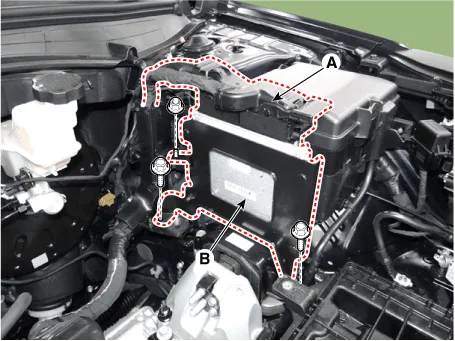
| 4. |
Disconnect the ECM Connector (A).
|
| 5. |
Remove the ECM bracket assembly (B) after loosening the mounting bolt
and nuts,
|
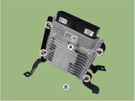
| 6. |
Remove the ECM after loosening the mounting nuts (A) and screw (B).
|
| Installation |
| 1. |
Install in the reverse order of removal.
|
| ECM Problem Inspection Procedure |
| 1. |
TEST ECM GROUND CIRCUIT : Measure resistance between ECM and chassis
ground using the backside of ECM harness connector as ECM side check
point. If the problem is found, repair it.
|
| 2. |
TEST ECM CONNECTOR : Disconnect the ECM connector and visually check
the ground terminals on ECM side and harness side for bent pins or poor
contact pressure. If the problem is found, repair it.
|
| 3. |
If problem is not found in steps 1 and 2, the ECM could be faulty. In
this case, make sure that there are no DTC's before replacing the ECM
with a new one, and then check the vehicle again. If DTC's are found,
examine them first before replacing the ECM.
|
| 4. |
RE-TEST THE ORIGINAL ECM : Install the original ECM (possibly broken)
into a known-good vehicle and check the vehicle. If the problem reoccurs,
replace the original ECM with a new one. If problem does not reoccur,
this is an intermittent problem.
(Refer to "Intermittent Problem Inspection Procedure" in Basic Inspection
Procedure.)
|
| Adjustment |
| • |
After replacing the ECM of the vehicle with the immobilizer, the following
procedure must be performed.
|
| 1) |
Perform "ECM Neutral Mode" procedure using diagnostic tool.
(Refer to Body Electrical System - "Immobilizer System")
|
| 2) |
After finishing "ECM Neutral Mode", perform "Key Teaching" procedure
using diagnostic tool.
(Refer to Body Electrical System - "Immobilizer System")
|
| – |
Perform "Key Teaching" procedure using diagnostic tool.
(Refer to Body Electrical System - "Immobilizer System")
|
| • |
After replacing the ECM of the vehicle with the smart key system (button
start), the following procedure must be performed.
|
| 1) |
Perform "ECM Neutral Mode" procedure using diagnostic tool.
(Refer to Body Electrical System - "Smart Key")
|
| 2) |
After finishing "ECM Neutral Mode", turn IGN ON then OFF using the smart
key or start button. Then the ECM learns information on the smart key
automatically.
(Refer to Body Electrical System - "Smart Key")
|
| – |
Turn IGN ON then OFF using the smart key or start button. Then the ECM
learns information on the smart key automatically.
(Refer to Body Electrical System - "Smart Key")
|
|

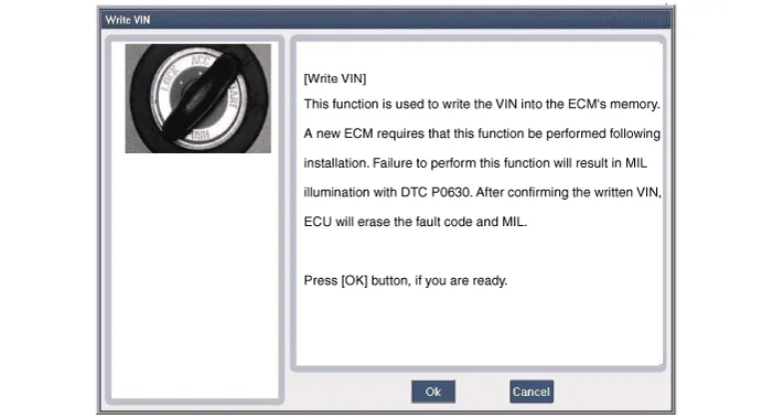
| 1. |
Select "VIN Writing" function in "Vehicle S/W Management".
|
| 2. |
Select "Write VIN" in "ID Register" menu.
|
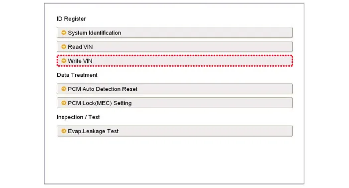
| 3. |
Enter the VIN.
|

Description If the Gasoline Engine Control system components (sensors, ECM, injector, etc.) fail, interruption to the fuel supply or failure to supply the proper amount of fuel for various engine operating conditions will result.
Description and operation Description The Electronic Throttle Control (ETC) System consists of a throttle body with an integrated control motor and throttle position sensor (TPS).
Other information:
Hyundai Palisade (LX2) 2020-2026 Service Manual: Components and positions
Hyundai Palisade (LX2) 2020-2026 Service Manual: Description and operation
Description The cruise control system is engaged by the cruise "ON/OFF" main switch located on right of steering wheel column. The system has the capability to cruise, coast, accelerate and resume speed. It also has a safety interrupt, engaged upon depressing brake or shifting select lever.
Categories
- Manuals Home
- Hyundai Palisade Owners Manual
- Hyundai Palisade Service Manual
- Electrochromatic Mirror (ECM) with homelink system
- Removing and Storing the Spare Tire
- Rain Sensor
- New on site
- Most important about car
