Hyundai Palisade (LX2): Immobilizer System / Antenna Coil
Repair procedures
| Removal |
| 1. |
Disconnect the negative (-) battery terminal.
|
| 2. |
Remove the crash pad lower panel.
(Refer to Body - "Crash Pad Lower Panel")
|
| 3. |
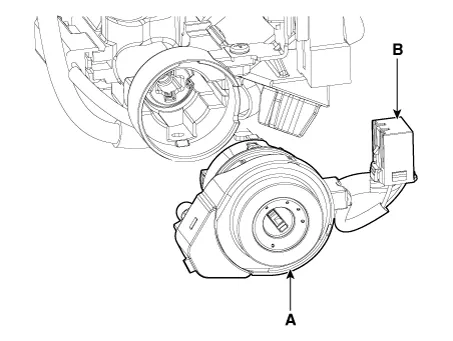
Disconnect the 6P connector (B) of the coil antenna and then remove
the coil antenna (A) after loosening the screw.
|
| Installation |
| 1. |
Install the coil antenna and connect the 6P connector.
|
| 2. |
Install the crash pad lower panel.
|
| 3. |
Connect the negative (-) battery terminal.
|
Repair procedures Removal 1. Disconnect the negative (-) battery terminal. 2. Remove the glove box housing.
Other information:
Hyundai Palisade (LX2) 2020-2026 Service Manual: General safety information and caution
Instructions (R-134a) When Handling Refrigerant 1. R-134a liquid refrigerant is highly volatile. A drop on the skin of your hand could result in localized frostbite. When handling the refrigerant, be sure to wear gloves.
Hyundai Palisade (LX2) 2020-2026 Service Manual: Description and operation
Description Surround View Monitor (SVM) is the system that allows video monitoring of 360 degrees around the vehicle. The system includes 4 ultra optical camera mounted around the vehicle (front, both sides, rear). The video from these cameras are applied with distortion compensation, time point conversion, and video me
Categories
- Manuals Home
- Hyundai Palisade Owners Manual
- Hyundai Palisade Service Manual
- Rain Sensor
- Rear Heater Unit
- PTG Spindle
- New on site
- Most important about car

Copyright © 2026 www.hpalisadelx.com - 0.0219