Hyundai Palisade (LX2): AVN System / USB jack
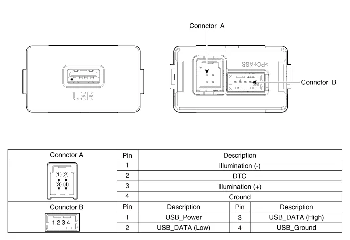
Schematic diagrams
| Circuit Diagram |
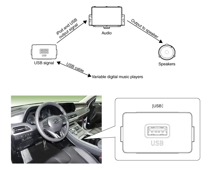
Description and operation
| Description |
Repair procedures
| Removal |
| 1. |
Disconnect the negative (-) battery terminal.
|
| 2. |
Remove the front console assembly.
(Refer to Body - Floor Console Assembly")
|
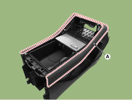
| 3. |
Remove the front console garnish (A).
|

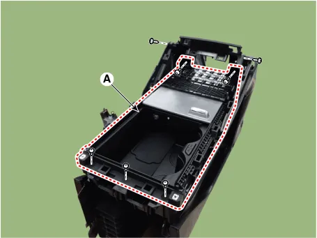
| 4. |
Remove the front console tray assembly (A).
|
| 5. |
Disconnect the connector (A).
|
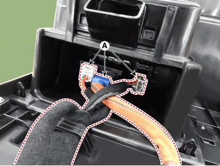
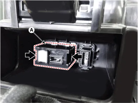
| 6. |
Remove the USB (A) by pushing the fixed clip in the direction of the
arrow as lillustration below.
|
| Installation |
| 1. |
Install the USB.
|
| 2. |
Install the front console assembly.
|
| 3. |
Connect the negative (-) battery connector.
|
Components and components location Components Repair procedures Removal 1. Disconnct the negative (-) battery terminal.
Components and components location Components 1. Remote control switch (LH : Audio + Voice) 2. Remote control switch (RH : Trip + Cruise) Schematic diagrams Circuit Diagram [Audio / Bluetooth / Voice] [Trip + Cruise] [Trip + Cruise + Smart cruise] Repair procedures Inspection 1.
Other information:
Hyundai Palisade (LX2) 2020-2026 Service Manual: Description and operating principle
Description and Operation Wireless Power Charger System During ACC or IG ON, battery voltage is supplied to the wireless power charger system to transmit an output of 5 W to mobile phone. Mobile phones certified with the wireless charging standard WPC (Qi 1.
Hyundai Palisade (LX2) 2020-2026 Service Manual: Description and operation
Description Surround View Monitor (SVM) is the system that allows video monitoring of 360 degrees around the vehicle. The system includes 4 ultra optical camera mounted around the vehicle (front, both sides, rear). The video from these cameras are applied with distortion compensation, time point conversion, and video me
Categories
- Manuals Home
- Hyundai Palisade Owners Manual
- Hyundai Palisade Service Manual
- Removing and Storing the Spare Tire
- Electronic Child Safety Lock System
- How to reset the power liftgate
- New on site
- Most important about car
