Hyundai Palisade: AVN System / Steering Wheel Remote Controller (SWRC)
Hyundai Palisade (LX2) 2020-2025 Service Manual / Body Electrical System / AVN System / Steering Wheel Remote Controller (SWRC)
Components and components location
| Components |
| 1. Remote control switch (LH
: Audio + Voice) |
2. Remote control switch (RH
: Trip + Cruise) |
Schematic diagrams
| Circuit Diagram |
[Audio / Bluetooth / Voice]
[Trip + Cruise]
[Trip + Cruise + Smart cruise]
Repair procedures
| Inspection |
| 1. |
Check for resistance between terminals in left switch position.
[Audio / Bluetooth]
|

| 2. |
Check for resistance between terminals in right switch position.
[Trip / Cruise]
|
| Removal |
| 1. |
Disconnect the negative (-) battery terminal.
|
| 2. |
Remove the driver airbag module.
(Refer to Restraint - "Driver Airbag (DAB) Module and Clock Spring")
|
| 3. |
Remove the steering wheel.
(Refer to Steering System - "Steering Column and Shaft")
|
| 4. |
Remove the steering wheel cover (A) after loosening the screws.
|
| 5. |
Loosen the screws and then disconnect the steering wheel remote control
switch connector.
|
| 6. |
Remove the remote control switchs (A).
|
| Installation |
| 1. |
Install the remote control switch on the steering wheel.
|
| 2. |
Install the steering wheel.
|
| 3. |
Reconnect the remote control switch connector and airbag connectors.
|

| 4. |
Install the driver airbag module.
|
| 5. |
Connect the negative (-) battery terminal.
|
 USB jack
Schematic diagrams
Circuit Diagram
Description and operation
Description
The AUX, iPod and USB JACK on the center console is for customers who like to
listen to external portable music players like the MP3, iPod, earphone, USB
memory stick, CD player and etc...

Other information:
Hyundai Palisade (LX2) 2020-2025 Service Manual: Front Wheel Transfer Assembly
Components and components location Components Location [Diesel 2.2] 1. Trasaxle assembly 2. Transfer assembly 3. Propeller shaft assembly 4. Coupling assembly [Gasoline 3.5, 3.8] 1...
Hyundai Palisade (LX2) 2020-2025 Service Manual: Drive Belt Tensioner
Repair procedures Removal and Installation • Be careful not to damage the parts located under the vehicle (floor under cover, fuel filter, fuel tank and canister) when raising the vehicle using the lift...
Categories
- Manuals Home
- 1st Generation Palisade Owners Manual
- 1st Generation Palisade Service Manual
- Child-Protector Rear Door Locks
- Wireless Cellular Phone Charging System
- Side view mirror adjustment, Folding the side view mirrors
- New on site
- Most important about car
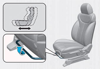
Manual adjustment
The front seat can be adjusted by using the levers located on the outside of the seat cushion. Before driving, adjust the seat to the proper position so that you can easily control the steering wheel, foot pedals and controls on the instrument panel.

Copyright © 2025 www.hpalisadelx.com