
Hyundai Palisade (LX2): Parking Distance Warning (PDW) / Ultrasonic Sensor
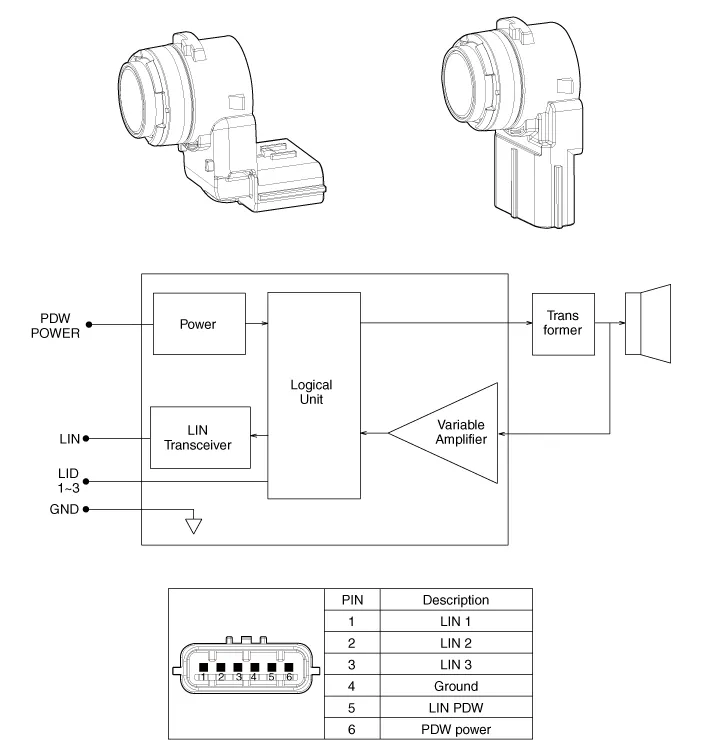
Schematic diagrams
| Schematic Diagrams |
Repair procedures
| Removal |
| 1. |
Remove the bumper cover.
(Refer to Body - "Front Bumper Cover")
(Refer to Body - "Rear Bumper Cover")
|
| 2. |
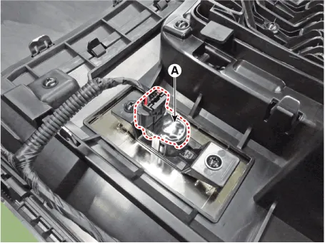
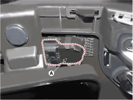
Disconnect the connector and remove the ultrasonic sensor (A).
[L - Type]
[I - Type]
|
| Installation |
| 1. |
Install the ultrasonic sensor.
|
| 2. |
Install the bumper cover.
|
Description • PDW consists of 8 sensors (front : 4 units, rear : 4 units) that are used to detect obstacles and transmit the result in three separate warning levels, the first, second and third to IBU via LIN communication.
Other information:
Hyundai Palisade (LX2) 2020-2026 Service Manual: Warning Indicator
Components and components location Components 1. Warning indicator 2. SVM camera Repair procedures Removal 1. Disconnect the negative (-) battery terminal. 2.
Hyundai Palisade (LX2) 2020-2026 Service Manual: Schematic diagrams
System Block Diagram Component Parts And Function Outline Component part Function Vehicle-speed sensor, ESP/ABS Control Module Converts vehicle speed to pulse. ECM Receives signals from sensor and control switches.
Categories
- Manuals Home
- Hyundai Palisade Owners Manual
- Hyundai Palisade Service Manual
- How to reset the power liftgate
- Emergency liftgate safety release
- Engine Control/Fuel System
- New on site
- Most important about car
