Hyundai Palisade (LX2): Automatic Transaxle Control System / Transaxle Control Module (TCM)
Components and components location
| Components Location |
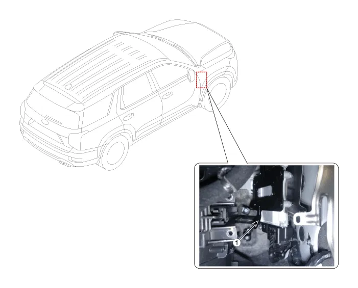
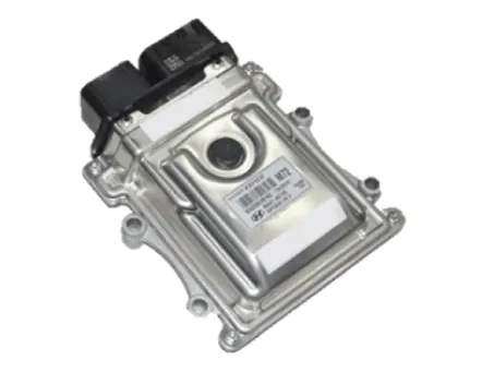
| 1. Transaxle control module(TCM) |
Description and operation
| Description |
| • |
Monitoring the vehicle's operating conditions to determine the optimal
gear setting.
|
| • |
Performing a gear change if the current gear setting differs from the
identified optimal gear setting.
|
| • |
Determining the need for damper clutch (D/C) activation and engages
the clutch accordingly.
|
| • |
Calculating the optimal line pressure level by constantly monitoring
the torque level and adjusts the pressure accordingly.
|
| • |
Diagnosing the automatic transaxle for faults and failures.
|
Schematic diagrams
| TCM Connector |
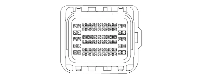
| TCM terminal function |
|
Pin |
Description |
Pin |
Description |
|
1 |
UD Clutch control solenoid valve (UD/C_VFS) |
34 |
Input speed sensor signal |
|
2 |
46 Clutch control solenoid valve (46/C_VFS) |
43 |
CAN High |
|
3 |
Line pressure control solenoid valve (LINE_VFS) |
52 |
CAN Low |
|
5 |
Torque converter control solenoid valve (T/CON_VFS) |
56 |
Output speed sensor power |
|
7 |
28 Brake control solenoid valve (28/B_VFS) |
57 |
Middle speed sensor power |
|
8 |
37R Clutch control solenoid valve (37R/C_VFS) |
58 |
Input speed sensor power |
|
9 |
OD Clutch & LR Brake Clutch control solenoid valve (OD/C & LR/B_VFS) |
65 |
Solenoid valve power 1 (2, 5, 7, 8) |
|
17 |
IG.1 |
66 |
Solenoid valve power 2 (1, 3, 9, 27) |
|
25 |
Oil temperature sensor (+) |
67 |
Power |
|
26 |
Oil temperature sensor (-) |
68 |
Power |
|
27 |
SS-A solenoid valve (SS-A_ON/OFF) |
71 |
Ground |
|
31 |
Middle speed sensor signal |
73 |
Ground |
|
32 |
Output speed sensor signal |
74 |
Ground |
| TCM terminal input / output signal |
|
Pin |
Description |
Condition |
Input / output value |
|
|
Type |
Level |
|||
|
1 |
UD Clutch control solenoid valve (UD/C_VFS) |
- |
Output |
0V/Battery voltage level |
|
9V < Battery voltage level < 16V |
||||
|
2 |
46 Clutch control solenoid valve (46/C_VFS) |
- |
Output |
0V/Battery voltage level |
|
9V < Battery voltage level < 16V |
||||
|
3 |
Line pressure control solenoid valve (LINE_VFS) |
- |
Output |
0V/Battery voltage level |
|
9V < Battery voltage level < 16V |
||||
|
5 |
Torque converter control solenoid valve (T/CON_VFS) |
- |
Output |
0V/Battery voltage level |
|
9V < Battery voltage level < 16V |
||||
|
7 |
28 Brake control solenoid valve (28/B_VFS) |
- |
Output |
0V/Battery voltage level |
|
9V < Battery voltage level < 16V |
||||
|
8 |
37R Clutch control solenoid valve (37R/C_VFS) |
- |
Output |
0V/Battery voltage level |
|
9V < Battery voltage level < 16V |
||||
|
9 |
OD
Clutch & LR Brake Clutch control solenoid valve (OD/C & LR/B_VFS) |
- |
Output |
0V/Battery voltage level |
|
9V < Battery voltage level < 16V |
||||
|
17 |
IG.1 |
On |
Power |
0V/Battery voltage level |
|
Off |
9V < Battery voltage level < 16V |
|||
|
25 |
Oil temperature sensor (+) |
ON |
Input |
0V/5V |
|
OFF |
||||
|
26 |
Oil temperature sensor (-) |
- |
Ground |
0V |
|
27 |
SS-A solenoid valve (SS-A_ON/OFF) |
High |
Output |
0V/Battery voltage level |
|
Low |
9V < Battery voltage level < 16V |
|||
|
31 |
Middle speed sensor signal |
High |
Input |
0.7V/1.4V |
|
Low |
||||
|
32 |
Output speed sensor signal |
High |
Input |
0.7V/1.4V |
|
Low |
||||
|
34 |
Input speed sensor signal |
High |
Input |
0.7V/1.4V |
|
Low |
||||
|
56 |
Output speed sensor power |
ON |
Power |
0V/9V |
|
OFF |
||||
|
57 |
Middle speed sensor power |
On |
Power |
0V/9V |
|
Off |
||||
|
58 |
Input speed sensor power |
On |
Power |
0V/9V |
|
Off |
||||
|
65 |
Solenoid valve power 1 |
- |
Power |
0V/Battery voltage level |
|
9V < Battery voltage level < 16V |
||||
|
66 |
Solenoid valve power 2 |
- |
Power |
0V/Battery voltage level |
|
9V < Battery voltage level < 16V |
||||
|
67 |
Power |
On |
Power |
0V/Battery voltage level |
|
Off |
9V < Battery voltage level < 16V |
|||
|
68 |
Power |
On |
Power |
0V/Battery voltage level |
|
Off |
9V < Battery voltage level < 16V |
|||
|
71 |
Ground |
- |
Ground |
0V |
|
73 |
Ground |
- |
Ground |
0V |
|
74 |
Ground |
- |
Ground |
0V |
Repair procedures
| Inspection |
| 1. |
TCM ground circuit test : Measure the resistance between TCM and chassis
ground.
(Inspect the terminal connected to the chassis ground with the back
of harness connector as the inspection point of TCM side.)
|
| 2. |
TCM connector test : Disconnect the TCM connector and visually check
the ground terminals on TCM side and harness side for bent pins or poor
contact pressure.
|
| 3. |
If problem is not found in Steps 1 and 2, the TCM could be faulty.
If so, replace the TCM with a new one, and then check the vehicle again.
If the vehicle operates normally then the problem was likely with the
TCM.
|
| 4. |
Reinspection of original TCM : Install the original TCM (probably broken)
into a known-good vehicle and check the vehicle. If the problem occurs
again, replace the original TCM with a new one.
If the problem does not reoccur, this is an intermittent problem and
other part may be faulty.
|
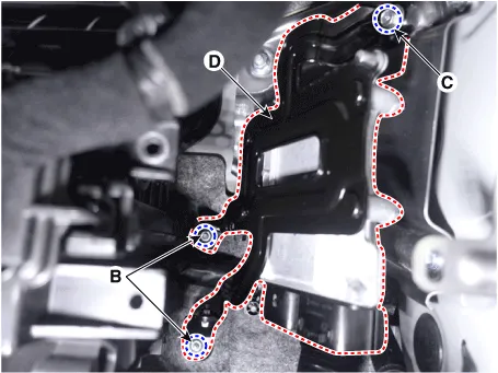
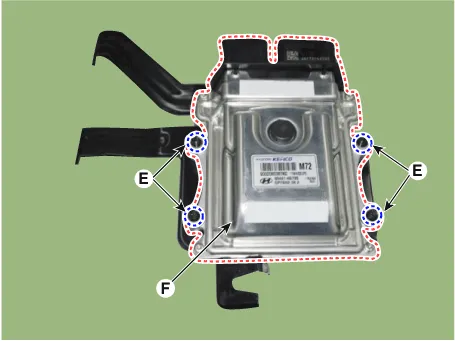
| Removal |
| 1. |
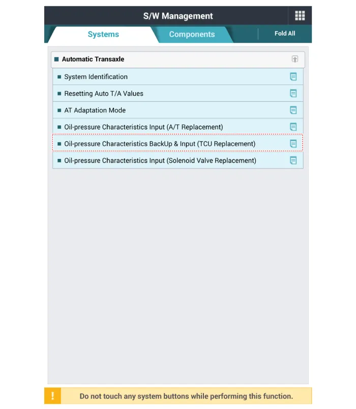
Perform the oil pressure characteristics backup procedure using the
diagnostic tool when replacing with a new TCM.
|
| 2. |
Turn ignition switch OFF and disconnect the negative (-) battery cable.
|
| 3. |
Remove the glove box.
(Refer to Body (Interior and Exterior) - "Glove Box")
|
| 4. |
Remove the integrated body control unit (IBU).
(Refer to Body Electical System - "Integrated Body Control Unit (IBU)")
|
| 5. |
Remove the intergrated control module (ICM) relay box.
(Refer to Body Electrical System - "Fuse and Relay")
|
| 6. |
Remove the TCM
|

| Installation |
| 1. |
To install, reverse the removal procedure.
|
| 2. |
Perform the oil pressure characteristics input procedure using the diagnostic
tool when replacing with a new TCM.
|

| 3. |
In order to avoid any problem including sense of starting delay of the
transaxle and shock at acceleration and vehicle start, make sure to
process learning for TCM after replacing the transaxle / TCM.
(Refer to Automatic Transaxle Control System - "Repair Procedures")
|
Adjustment TCM Learning 1. Overview and purpose of learning 1) The purpose is to ensure the initial operation safety by correcting the oil pressure differences between transmissions.
Description and operation Description Controls the 4 position of P(Parking), R, N, D using the rotation of the motor of according to the electric signal when the shift button is operated.
Other information:
Hyundai Palisade (LX2) 2020-2025 Service Manual: Immobilizer Control Unit
Repair procedures Removal 1. Disconnect the negative (-) battery terminal. 2. Remove the glove box housing. (Refer to Body - "Glove Box Housing Cover") 3.
Hyundai Palisade (LX2) 2020-2025 Service Manual: Evaporator Temperature Sensor
Description and operation Description The evaporator temperature sensor will detect the evaporator core temperature and interrupt compressor relay power in order to prevent evaporator from freezing by excessive cooling. Repair procedures Inspection 1.
Categories
- Manuals Home
- Hyundai Palisade Owners Manual
- Hyundai Palisade Service Manual
- Body (Interior and Exterior)
- Convenient Features of Your Vehicle
- Towing Service
- New on site
- Most important about car
