Hyundai Palisade: Suspension System / Tire Pressure Monitoring System

Hyundai Palisade (LX2) 2020-2024 Service Manual / Suspension System / Tire Pressure Monitoring System

Alignment

Repair procedures Front Wheel Alignment    • When using a commercially available computerized wheel alignment equipment to inspect the front wheel alignment, always position the vehicle on a level surface with the front wheels facing straight ahead...

Components and components location

..

Other information:

Hyundai Palisade (LX2) 2020-2024 Owner's Manual: Parking


Always come to a complete stop and continue to depress the brake pedal. Press the P button, apply the parking brake, and place the ignition switch in the LOCK/OFF position. Take the Key with you when exiting the vehicle. The gear is shifted to P (Park) position automatically for safety under the following conditions...

Hyundai Palisade (LX2) 2020-2024 Service Manual: Engine Control Module (ECM)


Schematic diagrams ECM Terminal and Input / Output Signal ECM Terminal Function Connector [A] Pin No Description Connected to 1 Ignition Coil (Cylinder #4) control output Ignition Coil (Cylinder #4) 2 Injector (Cylinder #3) [High] control output Injector (Cylinder #3) 3 Injector (Cylinder #5) [High] control output Injector (Cylinder #5) 4 Injector (Cylinder #1) [High] control output Injector (Cylinder #1) 5 Camshaft Position Sensor (CMPS) [Bank 2 / Exhaust] signal input Camshaft Position Sensor (CMPS) [Bank 2 / Exhaust] 6 Camshaft Position Sensor (CMPS) [Bank 2 / Intake] signal input Camshaft Position Sensor (CMPS) [Bank 2 / Intake] 7 Throttle Position Sensor (TPS) 2 signal input Throttle Position Sensor (TPS) 2 8 -   9 Rail Pressure Sensor (RPS) signal input Rail Pressure Sensor (RPS) 10 CVVT Oil Temperature Sensor (OTS) signal input CVVT Oil Temperature Sensor (OTS) 11 -   12 -   13 Sensor power (+5V) CVVT Oil Temperature Sensor (OTS) Manifold Absolute Pressure Sensor (MAPS) 14 -   15 -   16 -   17 -   18 -   19 ETC Motor [-] control output ETC Motor 20 Heated Oxygen Sensor (HO2S) [Bank 1 / Sensor 1] Heater control output Heated Oxygen Sensor (HO2S) [Bank 1 / Sensor 1] 21 Heated Oxygen Sensor (HO2S) [Bank 2 / Sensor 1] Heater control output Heated Oxygen Sensor (HO2S) [Bank 2 / Sensor 1] 22 Ignition Coil (Cylinder #5) control output Ignition Coil (Cylinder #5 23 Injector (Cylinder #6) [High] control output Injector (Cylinder #6) 24 Injector (Cylinder #2) [High] control output Injector (Cylinder #2) 25 Injector (Cylinder #4) [High] control output Injector (Cylinder #4) 26 Camshaft Position Sensor (CMPS) [Bank 1 / Exhaust] signal input Camshaft Position Sensor (CMPS) [Bank 1 / Exhaust] 27 Camshaft Position Sensor (CMPS) [Bank 1 / Intake] signal input Camshaft Position Sensor (CMPS) [Bank 1 / Intake] 28 Intake Air Temperature Sensor (IATS) signal input Intake Air Temperature Sensor (IATS) 29 Manifold Absolute Pressure Sensor (MAPS) signal input Manifold Absolute Pressure Sensor (MAPS) 30 -   31 -   32 -   33 -   34 Sensor power (+5V) Camshaft Position Sensor (CMPS) [Bank 1 / Exhaust] Camshaft Position Sensor (CMPS) [Bank 2 / Intake] 35 -   36 Sensor power (+5V) Camshaft Position Sensor (CMPS) [Bank 1 / Intake] Camshaft Position Sensor (CMPS) [Bank 2 / Exhaust] 37 -   38 Purge Control Solenoid Valve (PCSV) control output Purge Control Solenoid Valve (PCSV) 39 -   40 ETC Motor [+] control output ETC Motor 41 -   42 -   43 Ignition Coil (Cylinder #1) control output Ignition Coil (Cylinder #1) 44 Injector (Cylinder #6) [Low] control output Injector (Cylinder #6) 45 Injector (Cylinder #3) [Low] control output Injector (Cylinder #3) 46 Injector (Cylinder #2) [Low] control output Injector (Cylinder #2) 47 Sensor ground Camshaft Position Sensor (CMPS) [Bank 1 / Exhaust] Camshaft Position Sensor (CMPS) [Bank 2 / Intake] 48 Sensor ground Manifold Absolute Pressure Sensor (MAPS) Oil Pressure Sensor (OPS) 49 Sensor ground Camshaft Position Sensor (CMPS) [Bank 1 / Intake] Camshaft Position Sensor (CMPS) [Bank 2 / Exhaust] 50 -   51 -   52 -   53 -   54 Engine Coolant Temperature Sensor (ECTS) signal input Engine Coolant Temperature Sensor (ECTS) 55 Sensor Shield Crankshaft Position Sensor (CKPS) Knock Sensor (KS) #1 [Bank 1] Knock Sensor (KS) #2 [Bank 2] 56 Sensor power (+5V) Rail Pressure Sensor (RPS) 57 -   58 Sensor ground Engine Coolant Temperature Sensor (ECTS) Rail Pressure Sensor (RPS) 59 Sensor ground Throttle Position Sensor (TPS) 1 Throttle Position Sensor (TPS) 2 60 Variable Intake Solenoid (VIS) Valve 1 control output Variable Intake Solenoid (VIS) Valve 1 61 Variable Intake Solenoid (VIS) Valve 2 control output Variable Intake Solenoid (VIS) Valve 2 62 -   63 -   64 Ignition Coil (Cylinder #2) control output Ignition Coil (Cylinder #2) 65 Injector (Cylinder #1) [Low] control output Injector (Cylinder #1) 66 Injector (Cylinder #4) [Low] control output Injector (Cylinder #4) 67 Injector (Cylinder #5) [Low] control output Injector (Cylinder #5) 68 Crankshaft Position Sensor (CKPS) [High] signal input Crankshaft Position Sensor (CKPS) 69 Crankshaft Position Sensor (CKPS) [Low] signal input Crankshaft Position Sensor (CKPS) 70 -   71 -   72 Oil pressure switch signal input Oil Pressure Sensor (OPS) 73 -   74 -   75 Throttle Position Sensor (TPS) 1 signal input Throttle Position Sensor (TPS) 1 76 Knock Sensor (KS) [Bank 1] [Low] signal input Knock Sensor (KS) [Bank 1] 77 Knock Sensor (KS) [Bank 2] [Low] signal input Knock Sensor (KS) [Bank 2] 78 Sensor ground Heated Oxygen Sensor (HO2S) [Bank 2 / Sensor 2] 79 Rc/Rp (Pump Cell Voltage) Heated Oxygen Sensor (HO2S) [Bank 2 / Sensor 1] 80 VS+ (NERNST Cell Voltage) Heated Oxygen Sensor (HO2S) [Bank 2 / Sensor 1] 81 Heated Oxygen Sensor (HO2S) [Bank 2 / Sensor 2] signal input Heated Oxygen Sensor (HO2S) [Bank 2 / Sensor 2] 82 VS+ (NERNST Cell Voltage) Heated Oxygen Sensor (HO2S) [Bank 1 / Sensor 1] 83 Rc (Compensative Resistance) Heated Oxygen Sensor (HO2S) [Bank 1 / Sensor 1] 84 Oil Pressure Solenoid Valve control output Oil Pressure Solenoid Valve 85 Ignition Coil (Cylinder #6) control output Ignition Coil (Cylinder #6) 86 Ignition Coil (Cylinder #3) control output Ignition Coil (Cylinder #3) 87 Fuel Pressure Control Valve (FPCV) [High] control output Fuel Pressure Control Valve (FPCV) 88 Fuel Pressure Control Valve (FPCV) [Low] control output Fuel Pressure Control Valve (FPCV) 89 Heated Oxygen Sensor (HO2S) [Bank 2 / Sensor 2] Heater control output Heated Oxygen Sensor (HO2S) [Bank 2 / Sensor 2] 90 Heated Oxygen Sensor (HO2S) [Bank 1 / Sensor 2] Heater control output Heated Oxygen Sensor (HO2S) [Bank 1 / Sensor 2] 91 CVVT Oil Control Valve (OCV) [Bank 2 / Exhaust] control output CVVT Oil Control Valve (OCV) [Bank 2 / Exhaust] 92 CVVT Oil Control Valve (OCV) [Bank 1 / Exhaust] control output CVVT Oil Control Valve (OCV) [Bank 1 / Exhaust] 93 Variable Force Solenoid (VFS) [Bank 2 / Intake] control output Variable Force Solenoid (VFS) [Bank 2 / Intake] 94 Variable Force Solenoid (VFS) [Bank 1 / Intake] control output Variable Force Solenoid (VFS) [Bank 1 / Intake] 95 -   96 Sensor power (+5V) Throttle Position Sensor (TPS) 1 Throttle Position Sensor (TPS) 2 97 Knock Sensor (KS) [Bank 1] [High] signal input Knock Sensor (KS) [Bank 1] 98 Knock Sensor (KS) [Bank 2] [High] signal input Knock Sensor (KS) [Bank 2] 99 Sensor ground Heated Oxygen Sensor (HO2S) [Bank 1 / Sensor 2] 100 -   101 Rc (Compensative Resistance) Heated Oxygen Sensor (HO2S) [Bank 2 / Sensor 1] 102 VS-/IP- (Common ground) Heated Oxygen Sensor (HO2S) [Bank 2 / Sensor 1] 103 Heated Oxygen Sensor (HO2S) [Bank 1 / Sensor 2] signal input Heated Oxygen Sensor (HO2S) [Bank 1 / Sensor 2] 104 VS-/IP- (Common ground) Heated Oxygen Sensor (HO2S) [Bank 1 / Sensor 1] 105 Rc/Rp (Pump Cell Voltage) Heated Oxygen Sensor (HO2S) [Bank 1 / Sensor 1] Connector [K] Pin No Description Connected to 1 ECM ground Chassis ground 2 ECM ground Chassis ground 3 Battery power (B+) Main Relay 4 ECM ground Chassis ground 5 Battery power (B+) Main Relay 6 Battery power (B+) Main Relay 7 -   8 -   9 -   10 -   11 -   12 -   13 Sensor ground A/C Pressure Transducer (APT) 14 Immobilizer communication line Immobilizer Control Module 15 Fuel Level Sender (FLS) signal input [Fuel pump] Fuel Level Sender (FLS) 16 -   17 -   18 -   19 -   20 Sensor power (+5V) Accelerator Position Sensor (APS) 1 21 Main Relay control output Main Relay 22 -   23 -   24 -   25 -   26 -   27 -   28 Accelerator Position Sensor (APS) 2 signal input Accelerator Position Sensor (APS) 2 29 -   30 -   31 -   32 Fuel Level Sender (FLS) signal input [Sub Fuel Sender] Sub Fuel Level Sender 33 Fuel Pump Relay control output Fuel Pump Relay 34 -   35 Sensor power (+5V) A/C Pressure Transducer (APT) 36 Sensor power (+5V) Accelerator Position Sensor (APS) 2 37 -   38 Vehicle speed signal input VDC control module 39 -   40 -   41 Start signal input Start Relay 42 -   43 -   44 -   45 -   46 -   47 Sensor ground Accelerator Position Sensor (APS) 2 48 -   49 Brake Switch [Test] signal input Brake Switch 50 -   51 -   52 Sensor ground Accelerator Position Sensor (APS) 1 53 -   54 -   55 -   56 -   57 -   58 -   59 -   60 P-CAN [Low] Other control module, Data Link Connector (DLC), Multi-Purpose Check Connector 61 -   62 -   63 -   64 A/C Pressure Transducer (APT) signal input A/C Pressure Transducer (APT) 65 -   66 -   67 -   68 -   69 LIN (Local Interconnect Network) Serial Bus Line Battery Sensor 70 -   71 Cooling Fan Relay control output Cooling Fan Relay 72 Engine speed signal output Integrated Body Control Unit (IBU) 73 -   74 -   75 -   76 -   77 P-CAN [High] Other control module, Data Link Connector (DLC), Multi-Purpose Check Connector 78 -   79 Start Relay control output Start Relay 80 -   81 -   82 Accelerator Position Sensor (APS) 1 signal input Accelerator Position Sensor (APS) 1 83 Brake Switch [Light] signal input Brake Switch 84 -   85 -   86 -   87 -   88 -   89 -   90 -   91 -   ECM Terminal Input/ Output signal Connector [A] Pin No  Description Condition Type Level 1 Ignition Coil (Cylinder #4) control output Idle Pulse Vpeak = 400V Frequency : 0 - 58...

Categories

Manual adjustment

The front seat can be adjusted by using the levers located on the outside of the seat cushion. Before driving, adjust the seat to the proper position so that you can easily control the steering wheel, foot pedals and controls on the instrument panel.
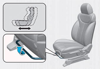
Hyundai Palisade. Manual adjustment

read more


Copyright © 2024 www.hpalisadelx.com