Hyundai Palisade (LX2): Tires/Wheels / Alignment
Repair procedures
| • |
When using a commercially available computerized wheel alignment
equipment to inspect the front wheel alignment, always position
the vehicle on a level surface with the front wheels facing
straight ahead.
|
| • |
Prior to inspection, make sure that the front suspension and
steering system are in normal operating condition and that the
tires are inflated to the specified pressure.
|
|
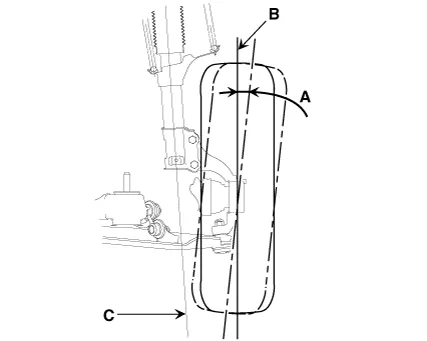
Toe

|
B - A > 0 : Toe in
B - A < 0 : Toe out
|
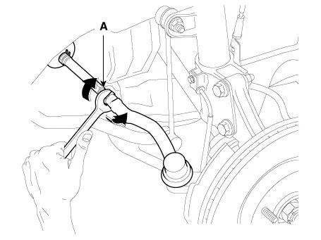
Toe Adjustment
| 1. |
Loosen the tie rod end lock nut.
|
| 2. |
Remove the bellows clip to prevent the bellows from being twisted.
|
| 3. |
Adjust the toe by screwing or unscrewing the tie rod. Toe adjustment
should be made by turning the right and left tie rods by the same amount.
|
Toe
Total : 0.1° ± 0.2°
Individual : 0.05° ± 0.1°
|
|
| 4. |
When completing the toe adjustment, install the bellows clip and tighten
the tie rod end lock nut to specified torque.
|
Tightening torque :
49.0 - 53.9 N.m (5.0 - 5.5 kgf.m, 36.2 - 39.8 lb-ft)
|
|
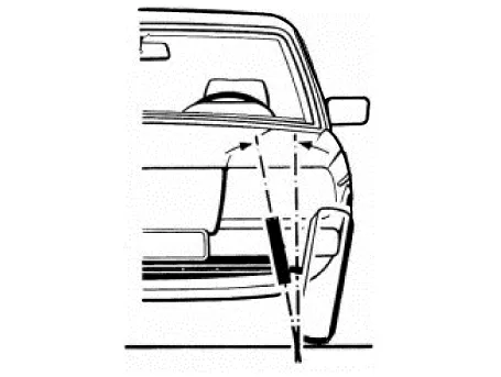
Camber
When the wheel tilts out at the top, then the camber is positive (+).
When the wheel tilts in at the top, then the camber is negative (-).
Camber and Caster are pre-set at the factory, so they do not need to be adjusted.
If the camber and caster are not within the standard value, replace or repair
the damaged parts and then inspect again.
ITEM
|
Description
|
A
|
Positive camber angle
|
B
|
True vertical
|
C
|
Strut centerline
|
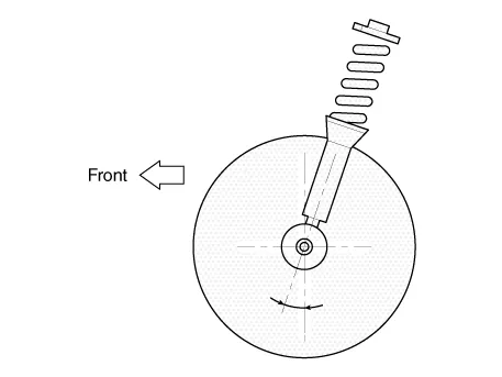
Caster
Caster is the tilting of the strut axis either forward or backward from vertical.
A backward tilt is positive (+) and a forward tilt is negative (-).
Caster is pre-set at the factory and doesn't need to be adjusted. If the caster
is not within the standard value, replace the bent or damaged parts.
King-pin angle
|
King-pin : 13.33° ± 0.5°
|
| • |
The worn loose or damaged parts of the front suspension assembly
must be replaced prior to measuring front wheel alignment.
|
| • |
Caster are pre-set to the specified value at the factory and
don't need to be adjusted.
|
| • |
If the caster are not within specifications, replace bent or
damaged parts.
|
| • |
The difference of left and right wheels about the the caster
must be within the range of 0° ± 0.5°.
|
|
| • |
When using a commercially available computerized wheel alignment
equipment to inspect the rear wheel alignment, always position
the vehicle on a level surface.
|
| • |
Prior to inspection, make sure that the rear suspension system
is in normal operating condition and that the tires are inflated
to the specified pressure.
|
|
Toe
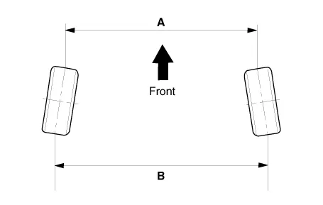
|
B - A > 0: Toe in (+)
B - A < 0: Toe out (-)
|
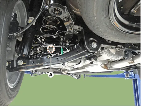
Toe adjustment
| 1. |
Loosen the nut holding the assist arm cam bolt (A).
|
| 2. |
Adjust rear toe by turning the rear assist arm cam bolt (A) clockwise
or counterclockwise. Toe adjustment should be made by turning the right
and left cam bolt by the same amount.
|
Toe
Total : 0.2° ± 0.2°
Individual : 0.1° ± 0.1°
|
|
| 3. |
When completing the toe adjustment, tighten the nut to specified torque.
|
Tightening torque :
137.3 - 156.9 N.m (14.0 - 16.0 kgf.m, 101.3 - 115.7 lb-ft)
|
|
Camber
| 1. |
Loosen the nut holding the rear lower arm cam bolt (A).
|
| 2. |
Adjust rear camber by turning the rear lower arm cam bolt (A) clockwise
or counter clockwise. Rear camber adjustment should be made by turning
the right and left cam bolt by the same amount.
|
Camber angle : - 1.0° ± 0.5°
|

|
| 3. |
When completing the toe adjustment, tighten the nut to specified torque.
|
Tightening torque :
137.3 - 156.9 N.m (14.0 - 16.0 kgf.m, 101.3 - 115.7 lb-ft)
|
|
Repair procedures
Hub nut tightening sequence
1.
Tighten the hub nuts as follows.
Tightening torque:
107.
Other information:
Description and operation
Description
The PTC (Positive Temperature Coefficient) heater is installed at the exit or
the backside of the heater core.
The PTC heater is an electric heater using a PTC element as an auxiliary heating
device that supplements deficiency of interior heat source in highly effective
diesel engi
Specifications
Specifications
[BCW, BCA]
Items
Blind-Spot Collision Warning (BCW)
Blind-Spot Collision- Avoidance Assist (BCA)
Rated voltage
DC 12V
Operating voltage
9V - 16V
Operating speed
30 km/h


