Hyundai Palisade (LX2): Intake And Exhaust System / Surge Tank
Components and components location
| Components |
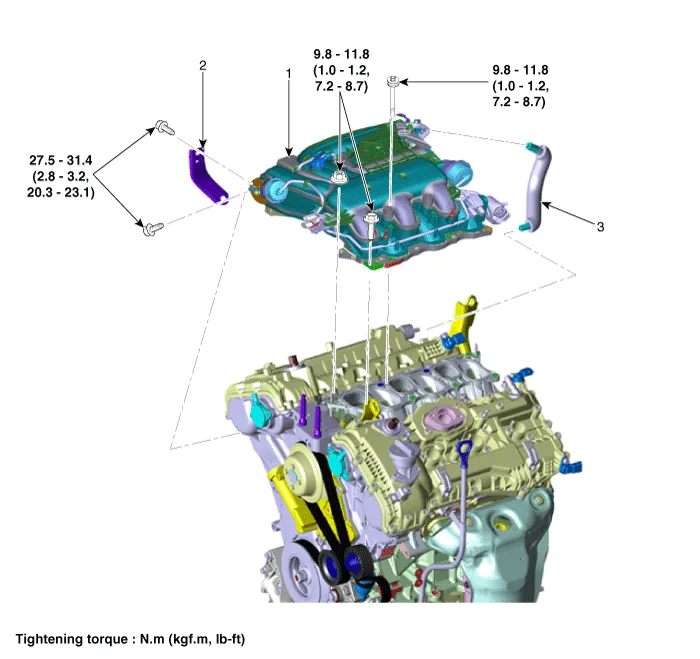
| 1. Surge tank 2. Surge tank stay |
3. Positive crankcase ventilation
(PCV) hose |
Repair procedures
| Removal and Installation |
| 1. |
Remove the engine cover.
(Refer to Engine and Transaxle Assembly - "Engine Cover")
|
| 2. |
Remove the air cleaner assembly.
(Refer to Intake And Exhaust System - "Air Cleaner")
|
| 3. |
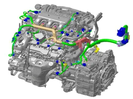
Disconnect the wiring connectors and harness clamps and remove the wiring
protector around the surge tank.
|
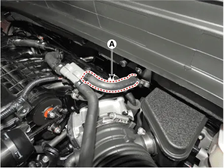
| 4. |
Disconnect the brake booster vacuum hose (A).
|
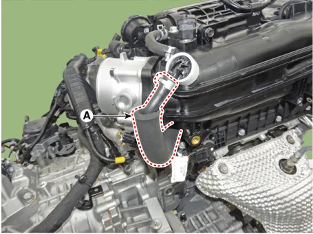
| 5. |
Disconnect the purge control solenoid valve (PCSV) hose (A).
|
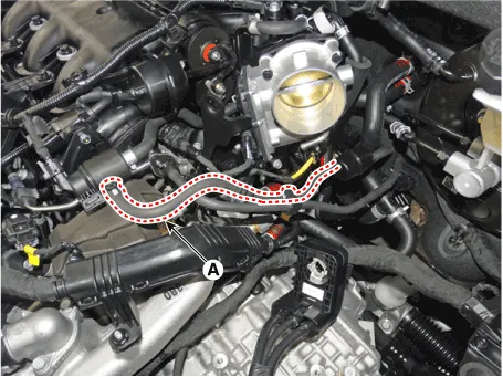
| 6. |
Disconnect the positive crankcase ventilation (PCV) hose (A).
|
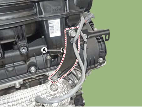
| 7. |
Remove the surge tank stay (A).
|
| 8. |
Remove the surge tank (A).
|
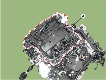
| 9. |
Install in the reverse order of removal.
|
Components and components location Components 1. Air cleaner body 2. Air cleaner cover 3. Air intake hose 4. Air cleaner element 5.
Repair procedures Removal and Installation VIS 1 [Intake Manifold] 1. Disconnect the battery negative terminal. 2.
Other information:
Hyundai Palisade (LX2) 2020-2026 Service Manual: Temperature Control Actuator
Description and operation Description The heater unit includes mode control actuator and temperature control actuator. The temperature control actuator is located at the heater unit. It regulates the temperature by the procedure as follows.
Hyundai Palisade (LX2) 2020-2026 Service Manual: Mode Control Actuator
Description and operation Description The mode control actuator is located at the heater unit. It adjusts the position of the mode door by operating the mode control actuator based on the signal of the A/C control unit. Pressing the mode select switch makes the mode control actuator shift in order of Vent → Bi-Level →
Categories
- Manuals Home
- Hyundai Palisade Owners Manual
- Hyundai Palisade Service Manual
- Resetting the Driver's Seat Memory System
- Rain Sensor
- Electronic Child Safety Lock System
- New on site
- Most important about car
