Hyundai Palisade (LX2): Intake And Exhaust System / Variable Intake Solenoid (VIS) Actuator
Repair procedures
| Removal and Installation |
| 1. |
Disconnect the battery negative terminal.
|
| 2. |
Remove the engine cover.
(Refer to Engine and Transaxle Assembly - "Engine Cover")
|
| 3. |
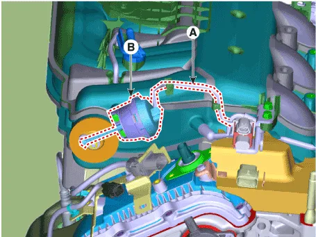
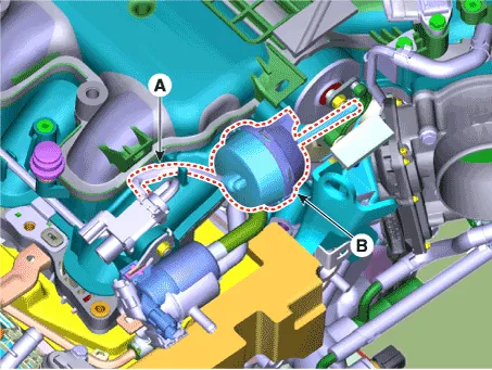
Disconnect the VIS actuator hose (A).
|
| 4. |
Remove the VIS actuator (B).
|
| 5. |
Install in the reverse order of removal.
|
| 1. |
Disconnect the battery negative terminal.
|
| 2. |
Remove the engine cover.
(Refer to Engine and Transaxle Assembly - "Engine Cover")
|
| 3. |
Disconnect the VIS actuator hose (A).
|
| 4. |
Remove the VIS actuator (B).
|
| 5. |
Install in the reverse order of removal.
|
Components and components location Components 1. Surge tank 2. Surge tank stay 3. Positive crankcase ventilation (PCV) hose Repair procedures Removal and Installation 1.
Components and components location Components 1. Intake manifold 2. Intake manifold gasket Repair procedures Removal and Installation 1.
Other information:
Hyundai Palisade (LX2) 2020-2026 Service Manual: Blower Unit
Components and components location Components Location 1. Blower unit assembly Components 1. Intake seal 2. Intake upper case 3. Intake actuator 4. Intake door 5.
Hyundai Palisade (LX2) 2020-2026 Service Manual: Front Radar Unit
Specifications Specification Item Specification Power supply (V) 12 Operation voltage (V) 9 - 16 Description and operation Description The smart cruise control unit is installed on the front right-hand side of the chass
Categories
- Manuals Home
- Hyundai Palisade Owners Manual
- Hyundai Palisade Service Manual
- Lift and Support Points
- Electronic Child Safety Lock System
- Automatic Transaxle Fluid (ATF)
- New on site
- Most important about car
