Hyundai Palisade: Crash Pad / Steering Column Shroud Panel
Components and components location
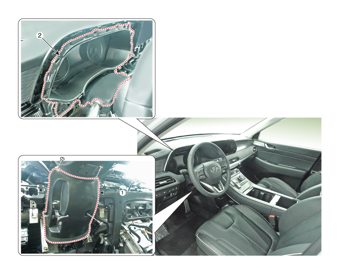
1. Steering column shroud lower
panel
|
2. Steering column shroud upper
panel
|
Repair procedures
[Steering column shroud upper panel]
| • |
When removing with a flat-tip screwdriver or remover, wrap protective
tape around the tools to prevent damage to components.
|
| • |
Put on gloves to prevent hand injuries.
|
|
| • |
Use a plastic panel removal tool to remove interior trim pieces
without marring the surface.
|
| • |
Take care not to bend or scratch the trim and panels.
|
|
| 1. |
Remove the front center fascia panel.
(Refer to Crash Pad - "Center fascia panel")
|
| 2. |
Remove the crash pad lower panel.
(Refer to Crash Pad - "Crash pad lower panel")
|
| 3. |
Loosen the mounting screws and remove the side air vent duct [LH] (A).
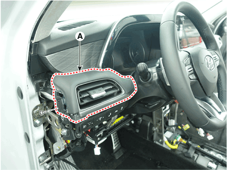
|
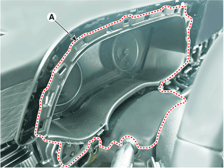
| 4. |
Loosen the mounting screws and remove the steering column shroud upper
panel (A).
|
| 5. |
To install, reverse removal procedure.
| •
|
Replace any damaged clips (or pin-type retainers).
|
|
|
[Steering column shroud lower panel]
| • |
When removing with a flat-tip screwdriver or remover, wrap protective
tape around the tools to prevent damage to components.
|
| • |
Put on gloves to prevent hand injuries.
|
|
| • |
Use a plastic panel removal tool to remove interior trim pieces
without marring the surface.
|
| • |
Take care not to bend or scratch the trim and panels.
|
|
| 1. |
Remove the crash pad lower panel.
(Refer to Crash Pad - "Crash pad lower panel")
|
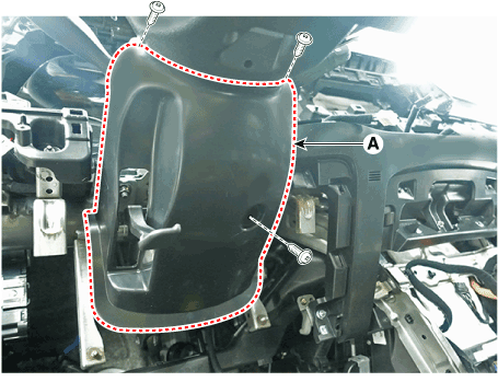
| 2. |
Loosen the mounting screws by turning the steering wheel to the left
and right, and remove the steering column shroud lower panel (A).
|
| 3. |
To install, reverse removal procedure.
| •
|
Replace any damaged clips (or pin-type retainers).
|
|
|
Components and components location
Component Location
1. Crash pad lower panel
Repair procedures
Replacement
•
When removing with a flat-tip screwdriver or remover, wrap protective
tape around the tools to prevent damage to components...
Components and components location
Component Location
[LH]
1. Crash pad side cover [LH]
[RH]
1...
Other information:
Repair procedures
Replacement
1.
Disconnect the negative (-) battery terminal.
2.
Remove the luggage side trim
(Refer to Body - "Luggage Side Trim ")
3.
Separate the rear blower motor connector (A), loosen the mounting screws
and remove the rear blower motor (B)...
Components and components location
Components
1. Air cleaner body
2. Air cleaner cover
3. Air intake hose
4. Air cleaner element
5. Air duct
6. Air intake shield
7. Breather hose
Repair procedures
Removal and Installation
Air Cleaner Assembly
1...
Categories
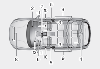
The SRS consists of the following
components:
1. Driver's front air bag module
2. Passenger's front air bag module
3. Side air bag modules
4. Curtain air bag modules
5. Retractor pre-tensioner
6. Air bag warning light
7. SRS control module (SRSCM)/
Rollover sensor
8. Front impact sensors
9. Side impact sensors
10.Side pressure sensors
11. Occupant classification system
12. Driver’s knee airbag module
read more


 Crash Pad Lower Panel
 Crash Pad Side Cover