Hyundai Palisade: Interior Lights / Vanity mirror lamp, Glove box lamp
Vanity mirror lamp

Opening the lid of the vanity mirror
will automatically turn on the mirror
light.
NOTICE
To prevent unnecessary charging
system drain, close the vanity mirror
cover after using the mirror.
Glove box lamp

The glove box lamp comes on when
the glove box is opened.
If the glove box is not closed, the
lamp will turn off after 20 minutes.
NOTICE
To prevent unnecessary charging
system drain, close the glove box
securely after using the glove box.
Rear lamp
Rear Room Lamp ():
Press either buttons to turn the room
lamp on or off.
Luggage compartment lamp
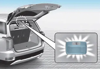
• ON () :
The luggage compartment lamp
stays on at all times...
Welcome light
When all doors (and liftgate) are
closed and locked, the puddle lamp
will come on for 15 seconds if the
door is unlocked by the remote key
or smart key or outside door handle
button...
Other information:
WARNING
Improperly positioned seat belts
may increase the risk of serious
injury in an accident.Take the following
precautions when adjusting
the seat belt:
Position the lap portion of the
seat belt as low as possible
across your hips, not on your
waist, so that it fits snugly...
Schematic diagrams
ECM Terminal and Input /
Output Signal
ECM Terminal Function
Connector [A]
Pin No
Description
Connected to
1
Ignition Coil (Cylinder #4) control output
Ignition Coil (Cylinder #4)
2
Injector (Cylinder #3) [High] control output
Injector (Cylinder #3)
3
Injector (Cylinder #5) [High] control output
Injector (Cylinder #5)
4
Injector (Cylinder #1) [High] control output
Injector (Cylinder #1)
5
Camshaft Position Sensor (CMPS) [Bank 2 / Exhaust] signal input
Camshaft Position Sensor (CMPS) [Bank 2 / Exhaust]
6
Camshaft Position Sensor (CMPS) [Bank 2 / Intake] signal input
Camshaft Position Sensor (CMPS) [Bank 2 / Intake]
7
Throttle Position Sensor (TPS) 2 signal input
Throttle Position Sensor (TPS) 2
8
-
9
Rail Pressure Sensor (RPS) signal input
Rail Pressure Sensor (RPS)
10
CVVT Oil Temperature Sensor (OTS) signal input
CVVT Oil Temperature Sensor (OTS)
11
-
12
-
13
Sensor power (+5V)
CVVT Oil Temperature Sensor (OTS)
Manifold Absolute Pressure Sensor (MAPS)
14
-
15
-
16
-
17
-
18
-
19
ETC Motor [-] control output
ETC Motor
20
Heated Oxygen Sensor (HO2S) [Bank 1 / Sensor 1] Heater control output
Heated Oxygen Sensor (HO2S) [Bank 1 / Sensor 1]
21
Heated Oxygen Sensor (HO2S) [Bank 2 / Sensor 1] Heater control output
Heated Oxygen Sensor (HO2S) [Bank 2 / Sensor 1]
22
Ignition Coil (Cylinder #5) control output
Ignition Coil (Cylinder #5
23
Injector (Cylinder #6) [High] control output
Injector (Cylinder #6)
24
Injector (Cylinder #2) [High] control output
Injector (Cylinder #2)
25
Injector (Cylinder #4) [High] control output
Injector (Cylinder #4)
26
Camshaft Position Sensor (CMPS) [Bank 1 / Exhaust] signal input
Camshaft Position Sensor (CMPS) [Bank 1 / Exhaust]
27
Camshaft Position Sensor (CMPS) [Bank 1 / Intake] signal input
Camshaft Position Sensor (CMPS) [Bank 1 / Intake]
28
Intake Air Temperature Sensor (IATS) signal input
Intake Air Temperature Sensor (IATS)
29
Manifold Absolute Pressure Sensor (MAPS) signal input
Manifold Absolute Pressure Sensor (MAPS)
30
-
31
-
32
-
33
-
34
Sensor power (+5V)
Camshaft Position Sensor (CMPS) [Bank 1 / Exhaust]
Camshaft Position Sensor (CMPS) [Bank 2 / Intake]
35
-
36
Sensor power (+5V)
Camshaft Position Sensor (CMPS) [Bank 1 / Intake]
Camshaft Position Sensor (CMPS) [Bank 2 / Exhaust]
37
-
38
Purge Control Solenoid Valve (PCSV) control output
Purge Control Solenoid Valve (PCSV)
39
-
40
ETC Motor [+] control output
ETC Motor
41
-
42
-
43
Ignition Coil (Cylinder #1) control output
Ignition Coil (Cylinder #1)
44
Injector (Cylinder #6) [Low] control output
Injector (Cylinder #6)
45
Injector (Cylinder #3) [Low] control output
Injector (Cylinder #3)
46
Injector (Cylinder #2) [Low] control output
Injector (Cylinder #2)
47
Sensor ground
Camshaft Position Sensor (CMPS) [Bank 1 / Exhaust]
Camshaft Position Sensor (CMPS) [Bank 2 / Intake]
48
Sensor ground
Manifold Absolute Pressure Sensor (MAPS)
Oil Pressure Sensor (OPS)
49
Sensor ground
Camshaft Position Sensor (CMPS) [Bank 1 / Intake]
Camshaft Position Sensor (CMPS) [Bank 2 / Exhaust]
50
-
51
-
52
-
53
-
54
Engine Coolant Temperature Sensor (ECTS) signal input
Engine Coolant Temperature Sensor (ECTS)
55
Sensor Shield
Crankshaft Position Sensor (CKPS)
Knock Sensor (KS) #1 [Bank 1]
Knock Sensor (KS) #2 [Bank 2]
56
Sensor power (+5V)
Rail Pressure Sensor (RPS)
57
-
58
Sensor ground
Engine Coolant Temperature Sensor (ECTS)
Rail Pressure Sensor (RPS)
59
Sensor ground
Throttle Position Sensor (TPS) 1
Throttle Position Sensor (TPS) 2
60
Variable Intake Solenoid (VIS) Valve 1 control output
Variable Intake Solenoid (VIS) Valve 1
61
Variable Intake Solenoid (VIS) Valve 2 control output
Variable Intake Solenoid (VIS) Valve 2
62
-
63
-
64
Ignition Coil (Cylinder #2) control output
Ignition Coil (Cylinder #2)
65
Injector (Cylinder #1) [Low] control output
Injector (Cylinder #1)
66
Injector (Cylinder #4) [Low] control output
Injector (Cylinder #4)
67
Injector (Cylinder #5) [Low] control output
Injector (Cylinder #5)
68
Crankshaft Position Sensor (CKPS) [High] signal input
Crankshaft Position Sensor (CKPS)
69
Crankshaft Position Sensor (CKPS) [Low] signal input
Crankshaft Position Sensor (CKPS)
70
-
71
-
72
Oil pressure switch signal input
Oil Pressure Sensor (OPS)
73
-
74
-
75
Throttle Position Sensor (TPS) 1 signal input
Throttle Position Sensor (TPS) 1
76
Knock Sensor (KS) [Bank 1] [Low] signal input
Knock Sensor (KS) [Bank 1]
77
Knock Sensor (KS) [Bank 2] [Low] signal input
Knock Sensor (KS) [Bank 2]
78
Sensor ground
Heated Oxygen Sensor (HO2S) [Bank 2 / Sensor 2]
79
Rc/Rp (Pump Cell Voltage)
Heated Oxygen Sensor (HO2S) [Bank 2 / Sensor 1]
80
VS+ (NERNST Cell Voltage)
Heated Oxygen Sensor (HO2S) [Bank 2 / Sensor 1]
81
Heated Oxygen Sensor (HO2S) [Bank 2 / Sensor 2] signal input
Heated Oxygen Sensor (HO2S) [Bank 2 / Sensor 2]
82
VS+ (NERNST Cell Voltage)
Heated Oxygen Sensor (HO2S) [Bank 1 / Sensor 1]
83
Rc (Compensative Resistance)
Heated Oxygen Sensor (HO2S) [Bank 1 / Sensor 1]
84
Oil Pressure Solenoid Valve control output
Oil Pressure Solenoid Valve
85
Ignition Coil (Cylinder #6) control output
Ignition Coil (Cylinder #6)
86
Ignition Coil (Cylinder #3) control output
Ignition Coil (Cylinder #3)
87
Fuel Pressure Control Valve (FPCV) [High] control output
Fuel Pressure Control Valve (FPCV)
88
Fuel Pressure Control Valve (FPCV) [Low] control output
Fuel Pressure Control Valve (FPCV)
89
Heated Oxygen Sensor (HO2S) [Bank 2 / Sensor 2] Heater control output
Heated Oxygen Sensor (HO2S) [Bank 2 / Sensor 2]
90
Heated Oxygen Sensor (HO2S) [Bank 1 / Sensor 2] Heater control output
Heated Oxygen Sensor (HO2S) [Bank 1 / Sensor 2]
91
CVVT Oil Control Valve (OCV) [Bank 2 / Exhaust] control output
CVVT Oil Control Valve (OCV) [Bank 2 / Exhaust]
92
CVVT Oil Control Valve (OCV) [Bank 1 / Exhaust] control output
CVVT Oil Control Valve (OCV) [Bank 1 / Exhaust]
93
Variable Force Solenoid (VFS) [Bank 2 / Intake] control output
Variable Force Solenoid (VFS) [Bank 2 / Intake]
94
Variable Force Solenoid (VFS) [Bank 1 / Intake] control output
Variable Force Solenoid (VFS) [Bank 1 / Intake]
95
-
96
Sensor power (+5V)
Throttle Position Sensor (TPS) 1
Throttle Position Sensor (TPS) 2
97
Knock Sensor (KS) [Bank 1] [High] signal input
Knock Sensor (KS) [Bank 1]
98
Knock Sensor (KS) [Bank 2] [High] signal input
Knock Sensor (KS) [Bank 2]
99
Sensor ground
Heated Oxygen Sensor (HO2S) [Bank 1 / Sensor 2]
100
-
101
Rc (Compensative Resistance)
Heated Oxygen Sensor (HO2S) [Bank 2 / Sensor 1]
102
VS-/IP- (Common ground)
Heated Oxygen Sensor (HO2S) [Bank 2 / Sensor 1]
103
Heated Oxygen Sensor (HO2S) [Bank 1 / Sensor 2] signal input
Heated Oxygen Sensor (HO2S) [Bank 1 / Sensor 2]
104
VS-/IP- (Common ground)
Heated Oxygen Sensor (HO2S) [Bank 1 / Sensor 1]
105
Rc/Rp (Pump Cell Voltage)
Heated Oxygen Sensor (HO2S) [Bank 1 / Sensor 1]
Connector [K]
Pin No
Description
Connected to
1
ECM ground
Chassis ground
2
ECM ground
Chassis ground
3
Battery power (B+)
Main Relay
4
ECM ground
Chassis ground
5
Battery power (B+)
Main Relay
6
Battery power (B+)
Main Relay
7
-
8
-
9
-
10
-
11
-
12
-
13
Sensor ground
A/C Pressure Transducer (APT)
14
Immobilizer communication line
Immobilizer Control Module
15
Fuel Level Sender (FLS) signal input [Fuel pump]
Fuel Level Sender (FLS)
16
-
17
-
18
-
19
-
20
Sensor power (+5V)
Accelerator Position Sensor (APS) 1
21
Main Relay control output
Main Relay
22
-
23
-
24
-
25
-
26
-
27
-
28
Accelerator Position Sensor (APS) 2 signal input
Accelerator Position Sensor (APS) 2
29
-
30
-
31
-
32
Fuel Level Sender (FLS) signal input [Sub Fuel Sender]
Sub Fuel Level Sender
33
Fuel Pump Relay control output
Fuel Pump Relay
34
-
35
Sensor power (+5V)
A/C Pressure Transducer (APT)
36
Sensor power (+5V)
Accelerator Position Sensor (APS) 2
37
-
38
Vehicle speed signal input
VDC control module
39
-
40
-
41
Start signal input
Start Relay
42
-
43
-
44
-
45
-
46
-
47
Sensor ground
Accelerator Position Sensor (APS) 2
48
-
49
Brake Switch [Test] signal input
Brake Switch
50
-
51
-
52
Sensor ground
Accelerator Position Sensor (APS) 1
53
-
54
-
55
-
56
-
57
-
58
-
59
-
60
P-CAN [Low]
Other control module, Data Link Connector (DLC), Multi-Purpose Check Connector
61
-
62
-
63
-
64
A/C Pressure Transducer (APT) signal input
A/C Pressure Transducer (APT)
65
-
66
-
67
-
68
-
69
LIN (Local Interconnect Network) Serial Bus Line
Battery Sensor
70
-
71
Cooling Fan Relay control output
Cooling Fan Relay
72
Engine speed signal output
Integrated Body Control Unit (IBU)
73
-
74
-
75
-
76
-
77
P-CAN [High]
Other control module, Data Link Connector (DLC), Multi-Purpose Check Connector
78
-
79
Start Relay control output
Start Relay
80
-
81
-
82
Accelerator Position Sensor (APS) 1 signal input
Accelerator Position Sensor (APS) 1
83
Brake Switch [Light] signal input
Brake Switch
84
-
85
-
86
-
87
-
88
-
89
-
90
-
91
-
ECM Terminal Input/ Output signal
Connector [A]
Pin No
Description
Condition
Type
Level
1
Ignition Coil (Cylinder #4) control output
Idle
Pulse
Vpeak = 400V
Frequency : 0 - 58...
Categories

Front air bags
Front air bags and the driver's knee
air bag are designed to inflate in a
frontal collision depending on the the
severity of impact of the front collision.


read more