Hyundai Palisade (LX2): Smart Key System / Smart Key Diagnostic
Repair procedures
| Inspection |
| 1. |
Problem in SMART KEY unit input.
|
| 2. |
Problem in SMART KEY unit.
|
| 3. |
Problem in SMART KEY unit output.
|
| 4. |
SMART KEY unit Input problem : switch diagnosis
|
| 5. |
SMART KEY unit problem : communication diagnosis
|
| 6. |
SMART KEY unit Output problem : antenna and switch output diagnosis
|
| 1. |
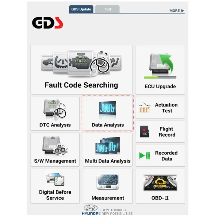
In the body electrical system, failure can be quickly diagnosed by using
the vehicle diagnostic system (Diagnostic tool).
The diagnostic system(Diagnostic tool) provides the following information.
|
| 2. |
If diagnose the vehicle by Diagnostic tool, select "DTC Analysis" and
"Vehicle".
|

| 3. |
If check current status, select the "Data Analysis" and "Car model".
|
| 4. |
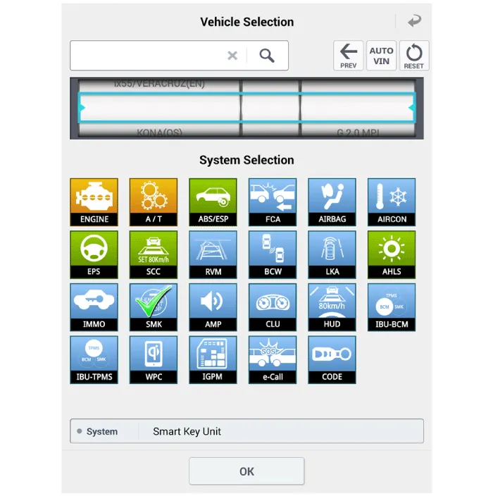
Select the SMK' to be checked in order to check the vehicle with the
tester.
|
| 5. |
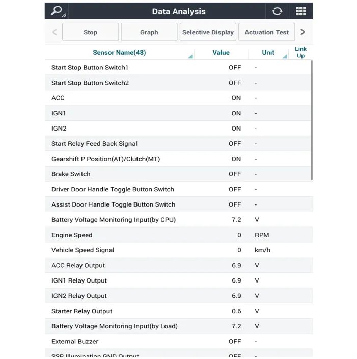
You can see the situation of each switch on scanner after connecting
the "current data" process.
|
| 1. |
Fault code searching that the each linked components operates normal.
|
| 2. |
Connect the cable of Diagnostic tool to the data link connector in driver
side crash pad lower panel.
|
| 3. |
Select the 'Fault Code Searching' and 'Car model'.
|

| 1. |
Connect the cable of Diagnostic tool to the data link connector in driver
side crash pad lower panel.
|
| 2. |
Select the 'Actuation Test' and 'Car model'.
|

| 3. |
Set the smart key near the related antenna and operate it with a Diagnostic
tool.
|
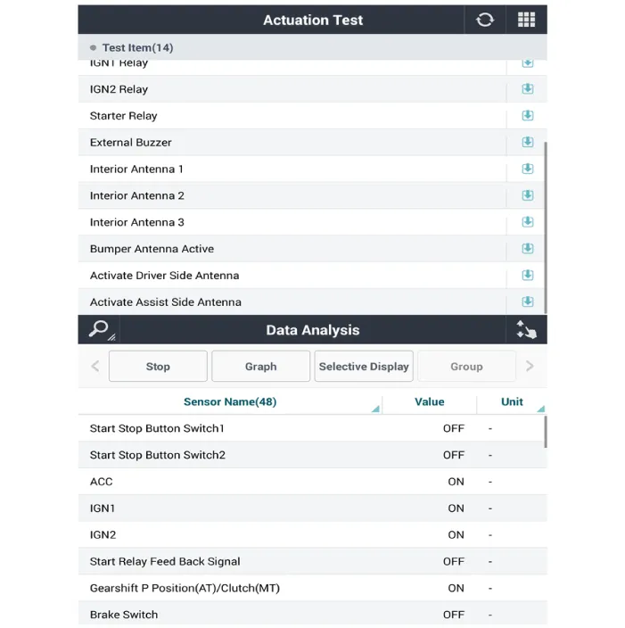
| 4. |
Set the smart key near the related antenna and operate it with a Diagnostic
tool.
|
| 5. |
If the LED of smart key is blinking, the smart key is normal.
|
| 6. |
If the LED of smart key is not blinking, check the voltage of smart
key battery.
|
| 7. |
Antenna actuation
|
| 1. |
Connect the cable of Diagnostic tool to the data link connector in driver
side crash pad lower panel.
|
| 2. |
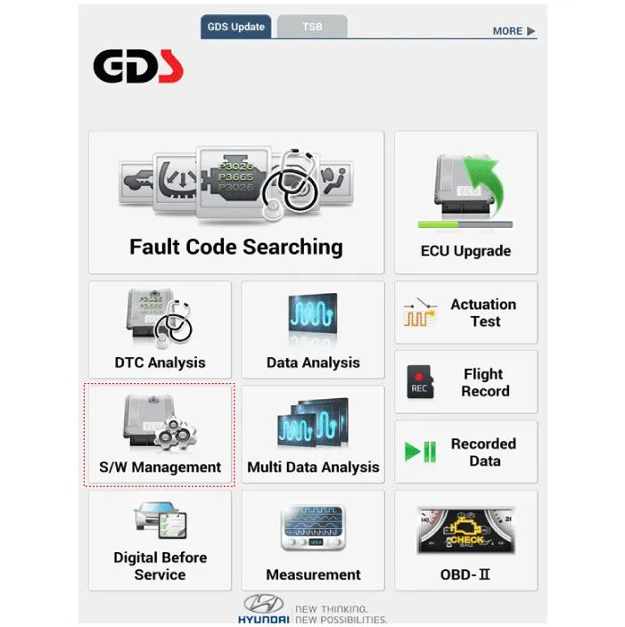
Select the 'S/W Management' and 'Car model'.
|

| 3. |
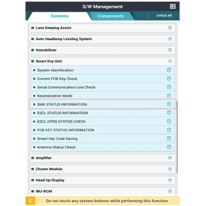
Select the 'Smart Key Unit' and 'Antenna Status Check'.
|

| 4. |
Set the smart key near the related antenna and operate it with a Diagnostic
tool.
|
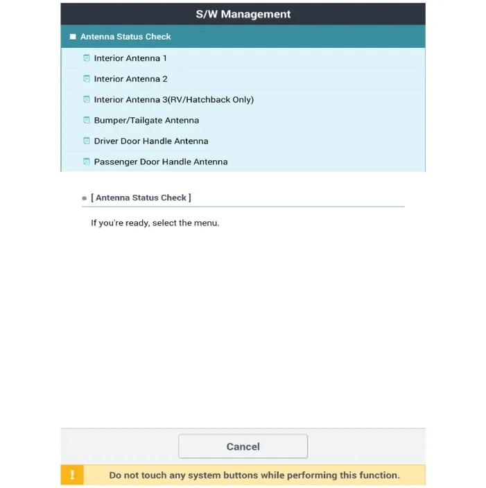
| 5. |
If the smart key runs normal , the related antenna, smart key (transmission,
reception) and exterior receiver are normal.
|
| 6. |
Antenna status
|
| 1. |
Connect the cable of Diagnostic tool to the data link connector in driver
side crash pad lower panel.
|
| 2. |
Select the 'S/W Management' and 'Car model'.
|

| 3. |
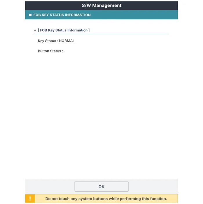
Select the 'Smart Key Unit' and 'FOB KEY STATUS IMFORMATION'.
|

| 1. |
Connect the cable of Diagnostic tool to the data link connector in driver
side crash pad lower panel.
|
| 2. |
Select the 'S/W Management' and 'Car model'.
|
| 3. |
Select the 'Smart Key Unit' and 'SMK STATUS INFORMATION'.
|
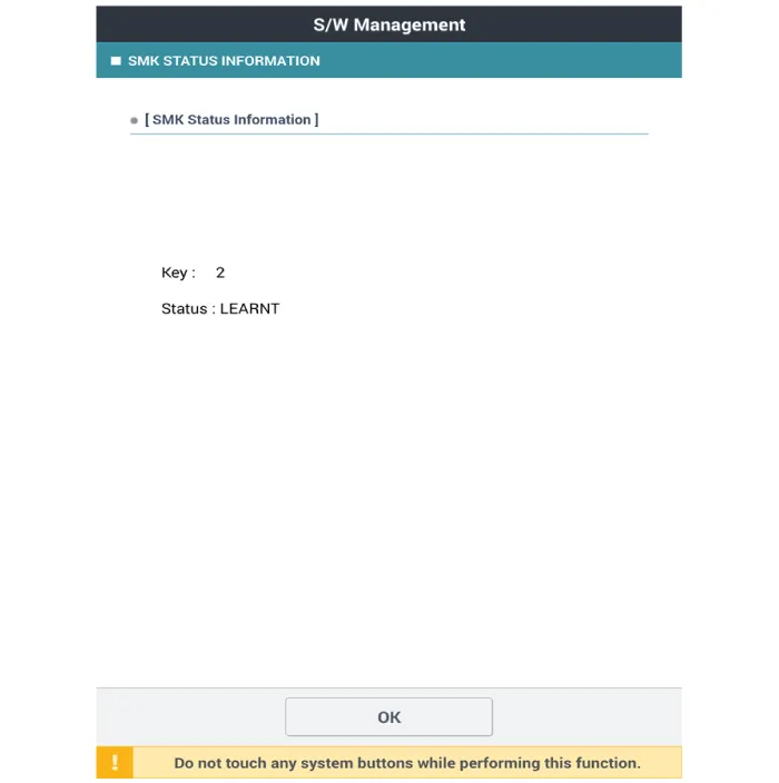
| 1. |
Connect the cable of Diagnostic tool to the data link connector in driver
side crash pad lower panel.
|
| 2. |
Select the 'S/W Management' and 'Car model'.
|

| 3. |
Select the 'Smart Key Unit' and 'Neutralization Mode'.
|


Components and components location Components (1) Connector Pin Information No Connector A Connector B Connector C 1 - GND_ECU Front wiper relay (Low)_output 2 - PDW-F power_output ESCL (+)_output 3 GND_Power ESCL (-)_output Start relay_output 4 PDW-R_Power_Output Front wiper high relay_output IGN1 relay_output 5 - PDW-R WIND_output Immobilizer antenna power_output 6 Rear washer switch_input - Immobilizer antenna ground_output 7 LIN4 (Rear seat remind) - - 8 P_CAN (Low) Rear view switch_input Interior1 antenna (+)_output 9 P_CAN (High) - Driver outside handle antenna(+)_output 10 - Wheel speed sensor_input - 11 B_CAN (Low) - Passenger outside handle antenna(+)_output 12 B_CAN (High) 3rd line sheet belt indicator RH_output - 13 SSB switch_input Passenger seat belt indicator_output Trunk interior antenna3(+)_output 14 Driver handle antenna switch_input Rear center seat belt indicator_output Immobilizer K-Line 15 P position_input (AT) - Bumper antenna (+)_output - 16 Fog switch_input LF searching_output Interior antenna2(+)_output 17 Light switch_input Auto light sensor signal_input IGN2_input 18 Front wiper INT volume switch_input Auto light sensor power_output IGN1_input 19 Multifunction switch_input ATM solenoid_output IGN2 relay_output 20 Right side mirror unfolding switch_oupout Puddle pocket lamp_output Battery_power 21 Right side mirror heater_output - Brake switch_input 22 Front washer switch_input SSB ring illumination_output Start feedback_input 23 Front wiper low switch_Input piezo buzzer_output Security indicator_output 24 LIN1 (PDW) SSB symbol illumination_output Interior1 (-)_output 25 LIN2 (Safety ECU) 3rd line sheet belt indicator_output Driver outside handle antenna (-)_output 26 LIN3 (Rain sensor) Wiper power relay_output - 27 PDW power_input Rear seat belt indicator RH_output Passenger outside handle antenna (-)_output 28 PDW_input Rear seat belt indicator LH_output ESCL COM 29 SSB switch1_input 3rd line sheet belt indicator LH_output Trunk Interior antenna3(-)_output 30 ESCL unlock_input Rear wiper relay_output ESCL Enable_output 31 Passenger outside handle switch_input Auto light sensor ground_output Bumper antenna (-)_output 32 PDW switch_input Wiper parking switch_input Interior antenna2 (-)_output 33 Sun roof Status_input ACC_input 34 Head lamp switch_input Mirror power_input 35 Front wiper switch_input ACC relay_output 36 Rear wiper switch_input ECU battery (+) 37 Mirror folding RH_output 38 Mirror RH VT_output
Other information:
Hyundai Palisade (LX2) 2020-2026 Service Manual: Heater Core
Repair procedures Replacement 1. Disconnect the negative (-) battery terminal. 2. Remove the heater and blower assembly. (Refer to Heater - "Heater Unit") 3.
Hyundai Palisade (LX2) 2020-2026 Service Manual: Specifications
Categories
- Manuals Home
- Hyundai Palisade Owners Manual
- Hyundai Palisade Service Manual
- Automatic Transaxle Fluid (ATF)
- Engine Mechanical System
- PTG Spindle
- New on site
- Most important about car
