Hyundai Palisade (LX2): Cruise Control System / Schematic diagrams
| System Block Diagram |
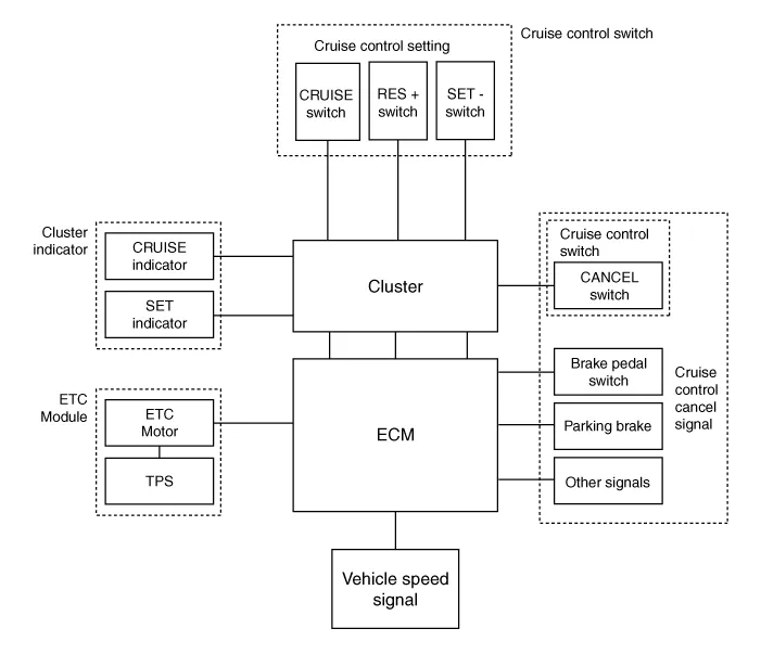
|
Component part |
Function |
|
|
Vehicle-speed sensor, ESP/ABS Control Module |
Converts vehicle speed to pulse. |
|
|
ECM |
Receives signals from sensor and control switches. |
|
|
Cruise control indicator |
Illuminate when CRUISE main switch is ON (Built into cluster) |
|
|
Cruise Control switches |
CRUISE switch |
Switch for automatic speed control power supply. |
|
RES+ switch |
Controls automatic speed control functions by Resume/Accel switch (Set/Coast
switch) |
|
|
SET- switch |
||
|
Cancel switches |
Cancel switch |
Sends cancel signals to ECM. |
|
Brake-pedal switch |
||
|
Transaxle range switch (A/T) |
||
|
ETC motor |
Regulates the throttle valve to the set opening by ECM. |
|
Cruise Control The cruise control system is engaged by the cruise "ON/OFF" main switch located on the right-hand side of steering wheel column.
Trouble Symptom Charts Trouble Symptom 1 Trouble Symptom 2 Trouble symptom Probable cause Remedy The set vehicle speed varies greatly upward or downward "Surging" (repeated alternating acceleration and deceleration) occurs after setting Malfunction of the vehicle speed sensor circuit Repair the vehicle speed sensor system, or replace the part Malfunction of ECM Check input and output signals at ECM Trouble Symptom 3 Trouble symptom Probable cause Remedy The CC system is not canceled when the brake pedal is depressed Damaged or disconnected wiring of the brake pedal switch Repair the harness or replace the brake pedal switch Malfunction of the ECM signals Check input and output signals at ECM Trouble Symptom 4 Trouble symptom Probable cause Remedy The CC system is not canceled when the shift lever is moved to the "N" position (It is canceled, however, when the brake pedal is depressed) Damaged or disconnected wiring of inhibitor switch input circuit Repair the harness or repair or replace the inhibitor switch Improper adjustment of inhibitor switch Malfunction of the ECM signals Check input and output signals at ECM Trouble Symptom 5 Trouble symptom Probable cause Remedy Cannot decelerate (coast) by using the "SET/–" switch Temporary damaged or disconnected wiring of "SET/–" switch input circuit Repair the harness or replace the "SET/–" switch Malfunction of the ECM signals Check input and output signals at ECM Trouble Symptom 6 Trouble symptom Probable cause Remedy Cannot accelerate or resume speed by using the "RES/+" switch Damaged or disconnected wiring, or short circuit, or "RES/+" switch input circuit Repair the harness or replace the "RES/+" switch Malfunction of the ECM signals Check input and output signals at ECM Trouble Symptom 7 Trouble symptom Probable cause Remedy CC system can be set while driving at a vehicle speed of less than 40km/h (25mph), or there is no automatic cancellation at that speed Malfunction of the vehicle-speed sensor circuit Repair the vehicle speed sensor system, or replace the part Malfunction of the ECM signals Check input and output signals at ECM Trouble Symptom 8 Trouble symptom Probable cause Remedy The cruise main switch indicator lamp does not illuminate (although CC system is normal) Damaged or disconnected bulb of cruise main switch indicator lamp Repair the harness or replace the part.
Other information:
Hyundai Palisade (LX2) 2020-2026 Service Manual: Temperature Control Actuator
Description and operation Description The heater unit includes mode control actuator and temperature control actuator. The temperature control actuator is located at the heater unit. It regulates the temperature by the procedure as follows.
Hyundai Palisade (LX2) 2020-2026 Service Manual: Climate Control Air Filter
Description and operation Description The climate control air filter is located in the blower unit. It eliminates foreign materials and odor. The particle filter performs a role as an odor filter as well as a conventional dust filter to ensure comfortable interior environment.
Categories
- Manuals Home
- Hyundai Palisade Owners Manual
- Hyundai Palisade Service Manual
- Rain Sensor
- Resetting the Driver's Seat Memory System
- Automatic Transaxle Fluid (ATF)
- New on site
- Most important about car
