Hyundai Palisade (LX2): Multifunction Switch / Repair procedures
Hyundai Palisade (LX2) 2020-2026 Service Manual / Body Electrical System / Multifunction Switch / Repair procedures
| Removal |
| 1. |
Disconnect the negative (-) battery terminal.
|
| 2. |
Remove the steering wheel.
(Refer to Steering System - "Steering Wheel")
|
| 3. |
Remove the steering column upper and lower shrouds.
(Refer to Body - "Steering Column Shroud Panel")
|
| 4. |
Remove the clock spring.
(Refer to Retraint - "Driver Airbag (DAB) Module and Clock Spring)
|
| 5. |
Disconnect the multifunction switch connector (A).
|
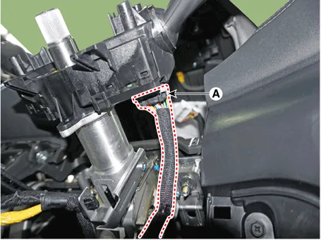
| 6. |
Loosen the screws (2EA) and then remove the multifunction switch assembly
(A).
|

| Installation |
| 1. |
Install the multifunction switch.
|
| 2. |
Install the clock spring and steering wheel.
|
| 3. |
Install the steering column upper and lower shrouds.
|
| 4. |
Install the steering wheel.
|
| Inspection |
Multifunction Switch Inspection
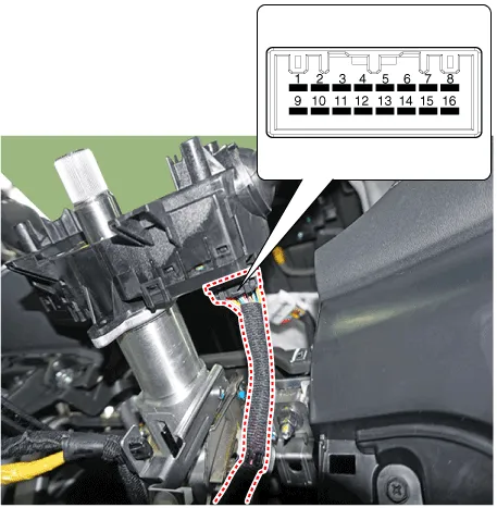
| 1. |
Check for continuity between the terminals in each switch position as
shown below.
|
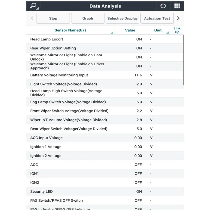
Inspection (With Diagnostic tool)
| 1. |
In the body electrical system, failure can be quickly diagnosed by using
the vehicle diagnostic system (Diagnostic tool).
The diagnostic system (Diagnostic tool) provides the following information.
|
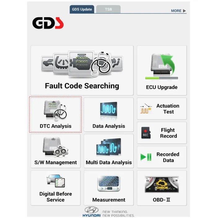
| 2. |
If diagnose the vehicle by Diagnostic tool, select "DTC Analysis" and
"Vehicle".
|
| 3. |
If check current status, select the "Data Analysis" and "Car model".
|
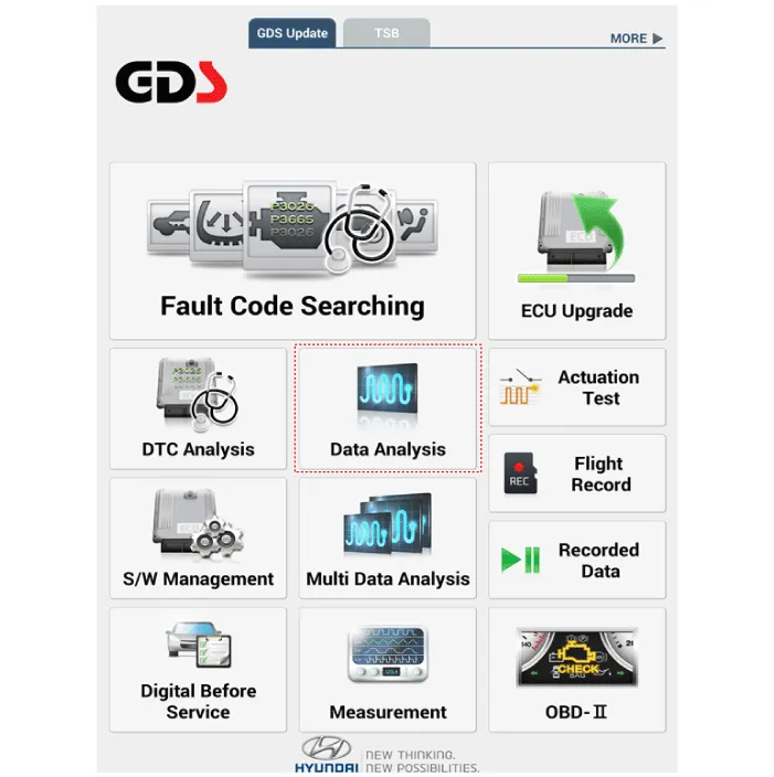
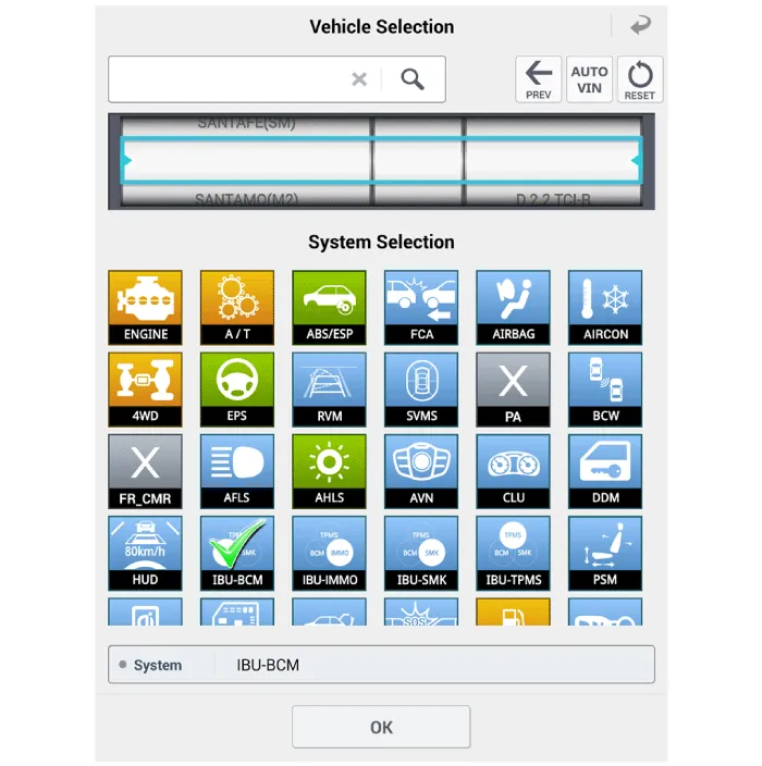
| 4. |
Select the 'IBU_BCM' to search the current state of the input/output
data.
|
Component 1. Steering column 2. Light switch 3. Wiper 4. Screw 5. Clock spring
Other information:
Hyundai Palisade (LX2) 2020-2026 Service Manual: Description and operation
Description • PDW consists of 8 sensors (front : 4 units, rear : 4 units) that are used to detect obstacles and transmit the result in three separate warning levels, the first, second and third to IBU via LIN communication.
Hyundai Palisade (LX2) 2020-2026 Service Manual: Parking/View Switch
Repair procedures Removal 1. Disconnect the negative (-) battery terminal. 2. Remove the floor console upper cover. (Refer to Body - "Floor Console Assembly") 3.
Categories
- Manuals Home
- Hyundai Palisade Owners Manual
- Hyundai Palisade Service Manual
- Rear Bumper Cover
- Convenient Features of Your Vehicle
- Removing and Storing the Spare Tire
- New on site
- Most important about car

Copyright © 2026 www.hpalisadelx.com - 0.0236