Hyundai Palisade (LX2): Fender / Repair procedures
Hyundai Palisade (LX2) 2020-2026 Service Manual / Body (Interior and Exterior) / Fender / Repair procedures
| Replacement |
|

| 1. |
Remove the front bumper.
(Refer to Front Bumper - "Front Bumper Cover")
|
| 2. |
Loosen the mounting bolts and then remove the front bumper side mounting
bracket (A).
|
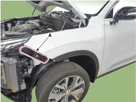
| 3. |
Loosen the mounting bolts and then remove the front bumper side mounting
bracket (A).
|
| 4. |
Remove the DRL (Daytime Running Lights) assembly.
(Refer to Body Electrical System - "DRL (Daytime Running Lights)")
|
| 5. |
Remove the front wheel guard.
(Refer to Body Side Molding - "Front Wheel Guard")
|
| 6. |
Remove the fender garnish.
(Refer to Body Side Molding - "Fender Garnish.")
|
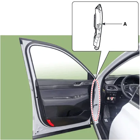
| 7. |
Remove the fender insulator (A).
|
| 8. |
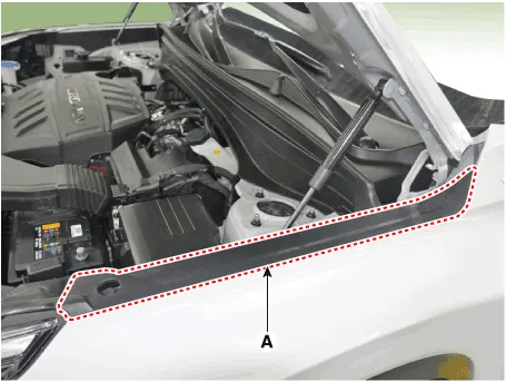
Loosen the mounting bolts and then remove the front bumper side mounting
bracket (A).
|
| 9. |
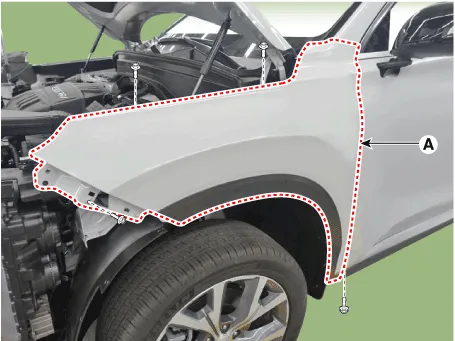
To install, reverse removal procedure.
|

Component Location 1. Fender assembly
Other information:
Hyundai Palisade (LX2) 2020-2026 Service Manual: Rear Temperature Control Actuator
Repair procedures Replacement 1. Disconnect the negative (-) battery terminal. 2. Remove the luggage side trim (Refer to Body - "Luggage Side Trim ") 3. Separate the rear temperature actuator connector (A), loosen the mounting screws a
Hyundai Palisade (LX2) 2020-2026 Service Manual: Heater & A/C Control Unit (Rear)
Components and components location Component Connector Pin Function Connector PIN No Pin Function Connector PIN No Pin Function A 1 Battery A 17 IGN2 2
Categories
- Manuals Home
- Hyundai Palisade Owners Manual
- Hyundai Palisade Service Manual
- How to reset the power liftgate
- Body (Interior and Exterior)
- Lift and Support Points
- New on site
- Most important about car

Copyright © 2026 www.hpalisadelx.com - 0.0176