Hyundai Palisade (LX2): Controller / Heater & A/C Control Unit (Rear)
Components and components location
| Component |

| Connector Pin Function |
|
Connector |
PIN No |
Pin Function |
Connector |
PIN No |
Pin Function |
|
A |
1 |
Battery |
A |
17 |
IGN2 |
|
2 |
ISG B+ |
18 |
IGN1 |
||
|
3 |
ILL+ (TAIL) |
19 |
Blower Motor (+) |
||
|
4 |
Sensor Ground REF (+5V) |
20 |
- |
||
|
5 |
Mode Control Actuator Feedback |
21 |
Mosfet (DRAIN F/B) |
||
|
6 |
Temperature Actuator Feedback |
22 |
Mosfet (GATE) |
||
|
7 |
Mode Control Actuator (Vent) |
23 |
Heater Switch _ LH |
||
|
8 |
Mode Control Actuator (Defrost) |
24 |
Indicator (HIGH) _ LH |
||
|
9 |
Temperature Control Actuator (Cool) |
25 |
Indicator (MID) _ LH |
||
|
10 |
Temperature Control Actuator (Warm) |
26 |
Indicator (LOW) _ LH |
||
|
11 |
Detent out (-) |
27 |
Heater Switch _ RH |
||
|
12 |
K - Line |
28 |
Indicator (HIGH) _ RH |
||
|
13 |
LIN Left |
29 |
Indicator (MID) _ RH |
||
|
14 |
Lin Right |
30 |
Indicator (LOW) _ RH |
||
|
15 |
- |
31 |
Sensor Ground |
||
|
16 |
ILL - (RHEO) |
32 |
Ground |
Repair procedures
| Replacement |
|

|

| 1. |
Disconnect the negative (-) battery terminal.
|
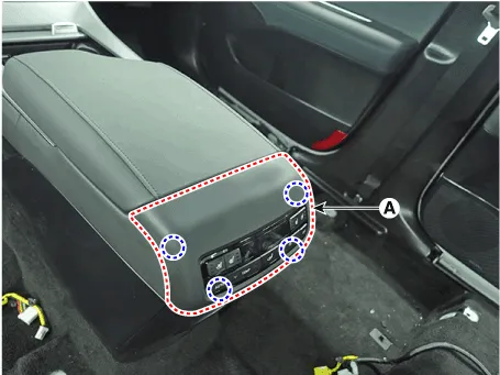
| 2. |
Using a flat-tip screwdriver or remover and remove the rear console
upper cover (A).
|
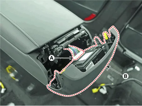
| 3. |
Press the lock pin and separate the rear console connector (A) and remove
the rear console upper cover (B).
|
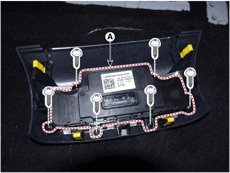
| 4. |
Loosen the mounting screws and remove the rear heater & A/C control
unit (A).
|
| 5. |
To install, reverse removal procedure.
|

Components and components location Component Connector Pin Function Connector PIN No Pin Function Connector PIN No Pin Function A 1 Battery A 21 IGN2 2 ISG B+ 22 IGN1 3 ILL+ (TAIL) 23 Blower Motor (+) 4 Sensor Ground REF (+5V) 24 Photo Sensor (-)_LEFT 5 Mode Control Actuator Feedback 25 Photo Sensor (-)_RIGHT 6 Temperature Actuator Feedback - Driver 26 Incar Sensor (+) 7 Intake Actuator Feedback 27 Incar Motor (-) 8 Evaporator Temperature Sensor (+) 28 PTC Relay 3 9 Ambient Temperature Sensor (+) 29 PTC Relay 3 10 Mode Control Actuator (Vent) 30 PTC On Signal 11 Mode Control Actuator (Defrost) 31 Detent out (-) 12 Temperature Control Actuator (Cool) - Driver 32 K - Line 13 Temperature Control Actuator (Warm) - Driver 33 P_CAN High 14 Intake Actuator (Fresh Air) 34 P_CAN Low 15 Intake Actuator (Recirculated Air) 35 Mosfet (DRAIN F/B) 16 HTD (Rear Defrost) 36 Mosfet (GATE) 17 Rear Defogging Swich 37 ECV + 18 Clean Signal 38 ECV - 19 Ionizer Diagnosis 39 Sensor Ground 20 ILL - (RHEO) 40 Ground Connector PIN No Pin Function Connector PIN No Pin Function B 1 Temperature Control Actuator Feedback - Passenger B 9 - 2 Temperature Control Actuator (Cool) - Passenger 10 - 3 Temperature Control Actuator (Warm) - Passenger 11 - 4 Defogging Actuator Feedback 12 Defogging Sensor TEMP 5 Defogging Actuator (Open) 13 Defogging Sensor SCK 6 Defogging Actuator (Close) 14 Defogging Sensor Data 7 - 15 - 8 Seat Signal PWM - Driver 16 Ground Repair procedures Self Diagnosis 1.
Other information:
Hyundai Palisade (LX2) 2020-2026 Service Manual: Description and operation
Description and Operation Blcok Diagram • This system monitors the driving situations through the radar and the camera. Thus, for a situation out of the sensing range, the system may not normally operate.
Hyundai Palisade (LX2) 2020-2026 Service Manual: Description and operation
Description The cruise control system is engaged by the cruise "ON/OFF" main switch located on right of steering wheel column. The system has the capability to cruise, coast, accelerate and resume speed. It also has a safety interrupt, engaged upon depressing brake or shifting select lever.
Categories
- Manuals Home
- Hyundai Palisade Owners Manual
- Hyundai Palisade Service Manual
- Electronic Child Safety Lock System
- General Tightening Torque Table
- Emergency liftgate safety release
- New on site
- Most important about car
