Hyundai Palisade (LX2): Rear Wiper/Washer / Rear Wiper Motor
Repair procedures
| Inspection |
| 1. |
Remove the connector from the rear wiper motor.
|
| 2. |
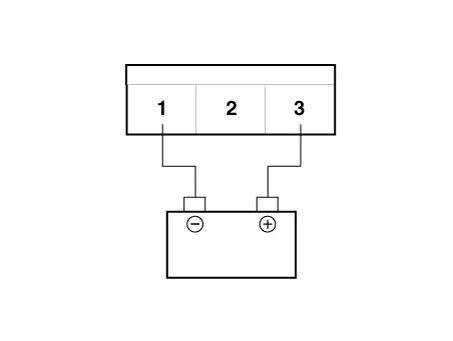
Connect battery positive (+) and negative (-) cables to terminals 2
and 1 respectively.
|
| 3. |
Check that the motor operates normally. Replace the motor if it operates
abnormally.
|

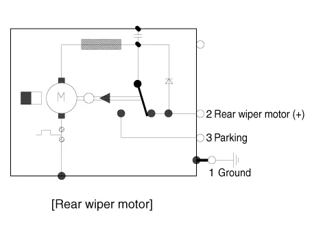
| 1. |
Operate the motor at low speed using the stalk control.
|
| 2. |
Stop the motor operation anywhere except at the off position by disconnecting
terminal 3.
|
| 3. |
Connect the positive (+) lead from the battery to terminal 3 and the
negative (-) lead to terminal 1.
|
| 4. |
Check that the motor stops running at the off position.
|
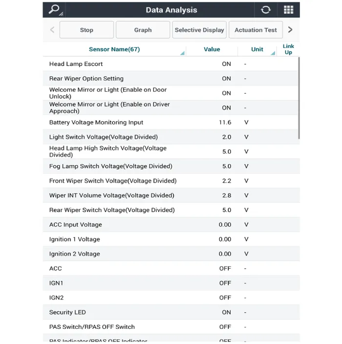
| 1. |
In the body electrical system, failure can be quickly diagnosed by using
the vehicle diagnostic system (Diagnostic tool).
The diagnostic system (Diagnostic tool) provides the following information.
|
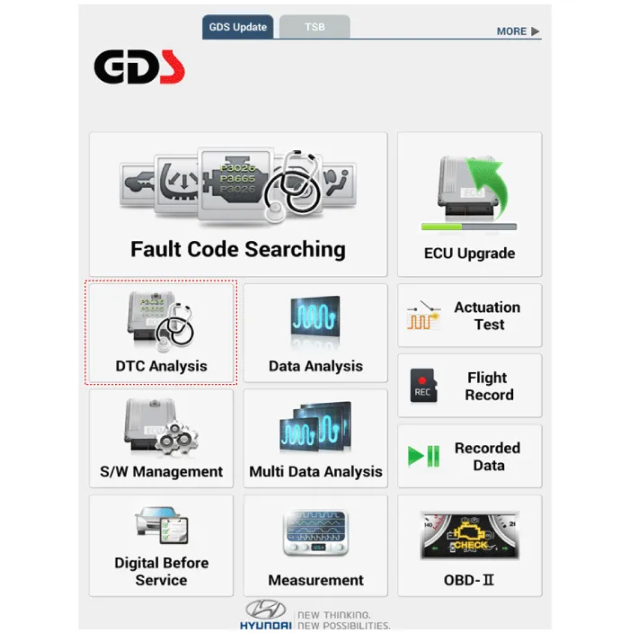
| 2. |
If diagnose the vehicle by Diagnostic tool, select "DTC Analysis" and
"Vehicle".
|
| 3. |
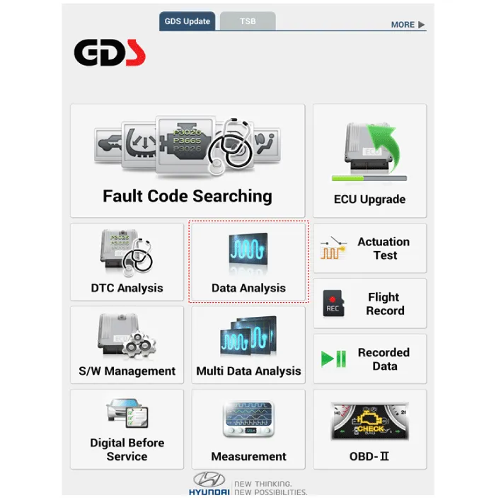
Select the 'Data Analysis'.
|
| 4. |
Select the 'IBU_BCM' to search the current state of the input/output
data.
|

| Removal |
| 1. |
Disconnect the negative (-) battery terminal.
|
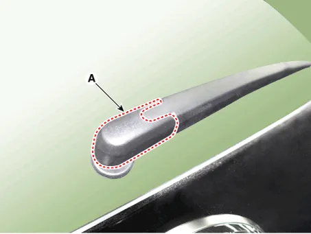
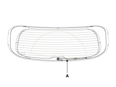
| 2. |
Detach the rear wiper cap (A).
|
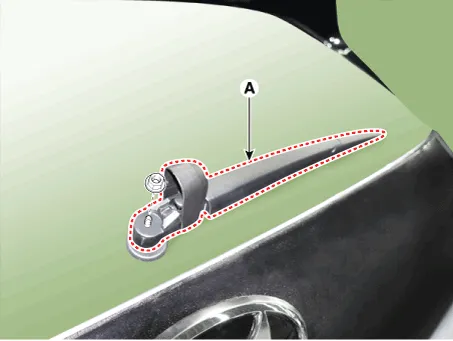
| 3. |
Remove the rear wiper arm & blade (A) after removing rear wiper nut.
|
| 4. |
Remove the tailgate trim.
(Refer to Body - "Tailgate Trim")
|
| 5. |
Disconnect the motor connector (A).
|
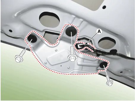
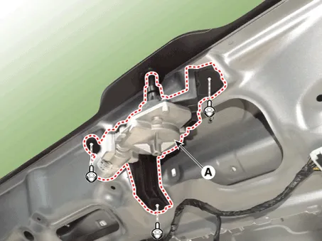
| 6. |
Remove the rear wiper motor (A) after loosening bolts .
|
| Installation |
| 1. |
Install the rear wiper motor assembly.
|
| 2. |
Install the tailgate trim.
|
| 3. |
Install the rear wiper arm cap after tighting the nut.
|
| 4. |
Set the rear wiper blade and to the lowest defogger heat line and tailgate
glass.
|
Component Location 1. Rear wiper arm nut 2. Rear wiper arm & blade 3. Rear wiper grommet 4. Rear wiper motor assembly
Repair procedures Inspection 1. Check for continuity between the terminals in each switch position as shown below.
Other information:
Hyundai Palisade (LX2) 2020-2026 Service Manual: A/C Pressure Transducer
Description and operation Description The A/C Pressure Transducer (APT) converts the pressure value of high pressure line into voltage value after measuring it. By converted voltage value, engine ECU controls the cooling fan by operating it high speed or low speed.
Hyundai Palisade (LX2) 2020-2026 Service Manual: Schematic diagrams
Trouble Symptom Charts Component Parts and Function Outline Component part Function Cruise Control Switch Input the set speed and distance to the SCC ECU. Instrument Cluster Display various information inputted from SCC.
Categories
- Manuals Home
- Hyundai Palisade Owners Manual
- Hyundai Palisade Service Manual
- Electrochromatic Mirror (ECM) with homelink system
- Electronic Child Safety Lock System
- Lift and Support Points
- New on site
- Most important about car
