Hyundai Palisade (LX2): Rear Bumper / Rear Bumper Cover
Components and components location
| Component Location |
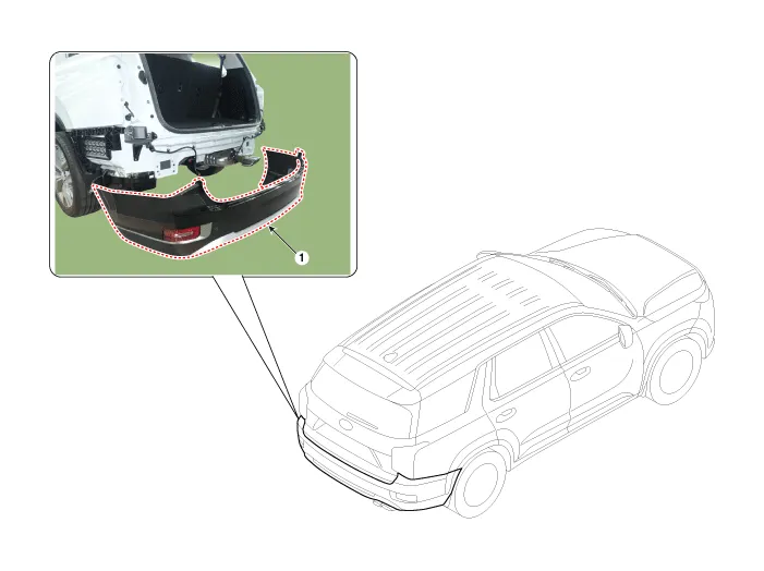
| 1. Rear bumper cover |
Repair procedures
| Replacement |
|
|
| 1. |
Using a flat-tip screwdriver or remover and remove the rear combination
lamp cover (A).
|
| 2. |
Remove the rear combination lamp (A) and separate the connector (B).
|
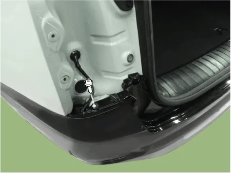
| 3. |
Loosen the rear bumper mounting clips.
|
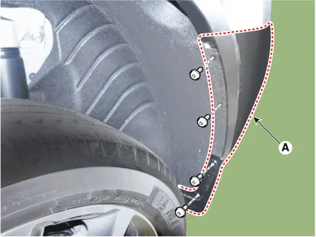
| 4. |
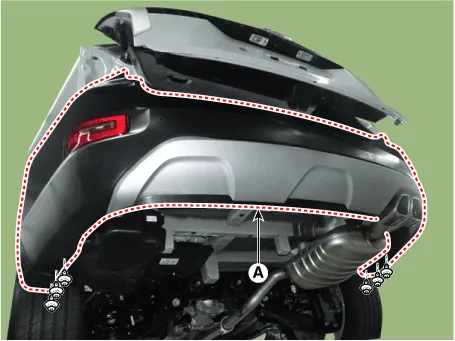
Loosen the mounting screws and retainer on the side of rear bumper (A),
detach the side part of rear bumper.
|
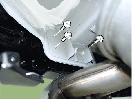
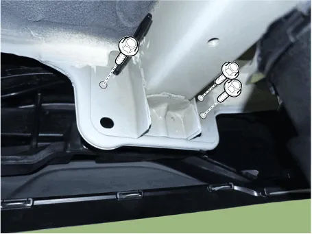
| 5. |
Loosen the rear bumper mounting bolts.
[RH]
[LH]
|
| 6. |
Loosen the mounting clips and remove the rear bumper cover (A).
|
| 7. |
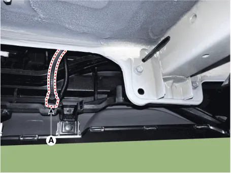
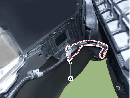
Press the lock pin and separate the BSD Connector (A).
|
| 8. |
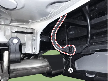
Press the lock pin and separate the rear bumper main connector (A).
|
| 9. |
To install, reverse removal procedure.
|
Components 1. Rear bumper cover 2. Rear side under cover 3. Rear bumper side braket
Components and components location Component Location 1. Rear bumper beam assembly
Other information:
Hyundai Palisade (LX2) 2020-2025 Service Manual: Evaporator Temperature Sensor
Description and operation Description The evaporator temperature sensor will detect the evaporator core temperature and interrupt compressor relay power in order to prevent evaporator from freezing by excessive cooling. Repair procedures Inspection 1.
Hyundai Palisade (LX2) 2020-2025 Service Manual: Troubleshooting
Diagnosis with Diagnostic tool 1. In the body electrical system, failure can be quickly diagnosed by using the vehicle diagnostic system (Diagnostic tool). The diagnostic system (Diagnostic tool) provides the following information.
Categories
- Manuals Home
- Hyundai Palisade Owners Manual
- Hyundai Palisade Service Manual
- Automatic Transaxle Fluid (ATF)
- Brake System
- Rear Heater Unit
- New on site
- Most important about car


