Hyundai Palisade: Engine Control System / Rail Pressure Sensor (RPS)
Hyundai Palisade (LX2) 2020-2025 Service Manual / Engine Control/Fuel System / Engine Control System / Rail Pressure Sensor (RPS)
Description and operation
| Description |
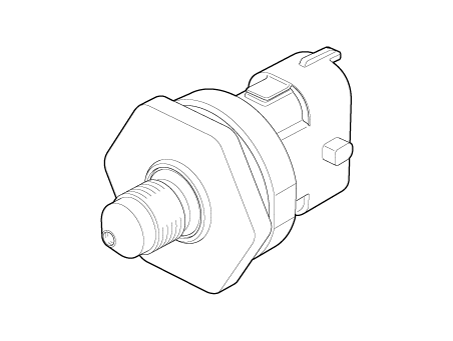
Installed on the delivery pipe, the Rail Pressure Sensor (RPS) measures the
instantaneous fuel pressure in the delivery pipe. The sensing element (Semiconductor
element) built in the sensor converts the pressure to voltage signal. By using
this signal, the ECM can control correct injection amount and timing and adjust
the fuel pressure with the fuel pressure regulator valve if the target pressure
is different from the actual pressure calculated by the RPS output signal.
Specifications
| Specification |
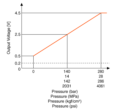
▷ Type : Piezo-electricity type
|
Pressure |
Output Voltage (V) [Vref=5V] |
|
|
bar |
[MPa (kgf/cm², psi)] |
|
|
0 |
0 (0, 0) |
0.5 |
|
140 |
14 (142, 2031) |
2.5 |
|
280 |
28 (286, 4061) |
4.5 |
Troubleshooting
| Signal Waveform |

Schematic diagrams
| Circuit Diagram |

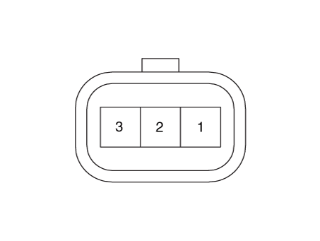
Harness Connector
Repair procedures
| Inspection |
| 1. |
Connect the diagnostic tool on the Data Link Connector (DLC).
|
| 2. |
Measure the output voltage of the RPS at idle and various engine speed.
|
||||||||||||||
| Removal |
| 1. |
Release the residual pressure in fuel line.
(Refer to Fuel Delivery System - "Release Residual Pressure in Fuel
Line")
|
| 2. |
Switch "OFF" the ignition and disconnect the negative (-) battery terminal.
|
| 3. |
Remove the intake manifold.
(Refer to Engine Mechanical System - "Intake Manifold")
|
| 4. |
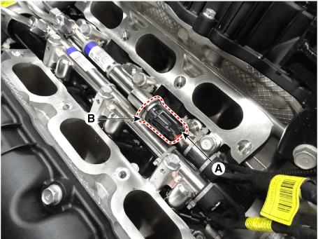
Disconnect the rail pressure sensor connector (A), and then remove the
sensor (B) from the delivery pipe.
|
| Installation |
|
| 1. |
Install in the reverse order of removal.
|
 Heated Oxygen Sensor (HO2S)
Description and operation
Description
Heated Oxygen Sensor (HO2S), consisting of zirconium and alumina, is installed
on both upstream and downstream of the Manifold Catalytic Converter (MCC) to
detect the air/fuel ratio and send it to the ECM...
 CVVT Oil Temperature Sensor (OTS)
Description and operation
Description
Continuous Variable Valve Timing (CVVT) system advances or retards the valve
timing of the intake and exhaust valve in accordance with the ECM control signal
which is calculated by the engine speed and load...
Other information:
Hyundai Palisade (LX2) 2020-2025 Owner's Manual: Drive Mode Integrated Control system (AWD)
The drive mode may be selected according to the driver's preference or road condition. Drive Mode The mode changes whenever the DRIVE MODE selection knob is rotated. • SMART mode : SMART mode automatically adjusts the driving mode (ECO ↔ COMFORT ↔ SPORT) in accordance with the driver's driving habits...
Hyundai Palisade (LX2) 2020-2025 Service Manual: Rear Glass Defogger Switch
Repair procedures Diagnosis with Diagnostic tool Diagnosis with Diagnostic tool 1. In the body electrical system, failure can be quickly diagnosed by using the vehicle diagnostic system (Diagnostic tool). The diagnostic system (Diagnostic tool) provides the following information...
Categories
- Manuals Home
- 1st Generation Palisade Owners Manual
- 1st Generation Palisade Service Manual
- Normal Maintenance Schedule (3.8 GDI)
- Side view mirror adjustment, Folding the side view mirrors
- Changing Tires
- New on site
- Most important about car
Seat Belt Warning Light
Seat belt warning light
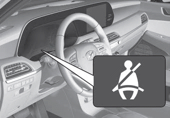
Driver's seat belt warning
As a reminder to the driver, the seat belt warning light will illuminate for approximately 6 seconds each time you place the ignition switch to the ON position regardless of belt fastening. At this time, if the seat belt is not fastened a warning chime will sound for 6 seconds.
Copyright © 2025 www.hpalisadelx.com

