Hyundai Palisade (LX2): Engine Control System / CVVT Oil Temperature Sensor (OTS)
Description and operation
| Description |

Specifications
| Specification |
|
Temperature |
Resistance (kΩ) |
|
|
°C |
°F |
|
|
-40 |
-40 |
41.74 - 54.54 |
|
-20 |
-4 |
14.13 - 16.83 |
|
0 |
32 |
5.28 - 6.3 |
|
25 |
77 |
1.88 - 2.14 |
|
80 |
176 |
0.31 - 0.33 |
|
140 |
284 |
0.07 - 0.08 |
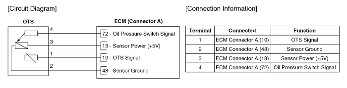
Schematic diagrams
| Circuit Diagram |
Repair procedures
| Inspection |
| 1. |
Switch "OFF" the ignition.
|
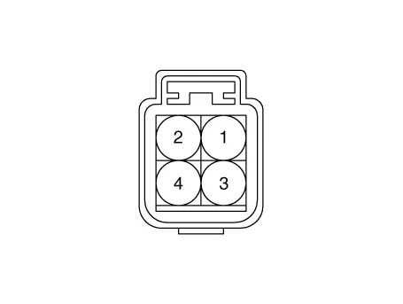
| 2. |
Disconnect the OTS connector.
|
| 3. |
Remove the OTS.
|
| 4. |
After immersing the thermistor of the sensor into engine coolant, measure
resistance between the OTS terminals 1 and 2.
|
| 5. |
Check that the resistance is within the specification.
|
|||||||||||||||||||||||
| Removal |
| 1. |
Refer to Engine Mechanical System - "Oil Pressure Sensor"
|
| Installation |
| 1. |
Refer to Engine Mechanical System - "Oil Pressure Sensor"
|
Description and operation Description Installed on the delivery pipe, the Rail Pressure Sensor (RPS) measures the instantaneous fuel pressure in the delivery pipe.
Description and operation Description Continuous Variable Valve Timing (CVVT) system advances or retards the valve timing of the intake and exhaust valve in accordance with the ECM control signal which is calculated by the engine speed and load.
Other information:
Hyundai Palisade (LX2) 2020-2026 Service Manual: Troubleshooting
Troubleshooting Problem Symptoms Table Before replacing or repairing air conditioning components, first determine if the malfunction is due to the refrigerant charge, air flow or compressor. Use the table below to help you find the cause of the problem.
Hyundai Palisade (LX2) 2020-2026 Service Manual: Surround View Monitor (SVM) Unit
Components and components location Components No Connector A 1 ACC 2 LED 3 EXT Ground 4 Y Shield 5 - 6 C-CAN Low 7
Categories
- Manuals Home
- Hyundai Palisade Owners Manual
- Hyundai Palisade Service Manual
- How to reset the power liftgate
- Engine Mechanical System
- Rain Sensor
- New on site
- Most important about car
