Hyundai Palisade (LX2): Panorama Sunroof / Panorama Sunroof Switch
Repair procedures
| Inspection |
| 1. |
Disconnect the negative (-) battery terminal.
|
| 2. |
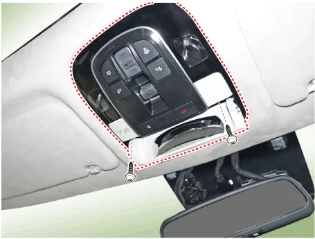
Open the sunglass case cover from the overhead console then remove screws
(2EA).
|
| 3. |
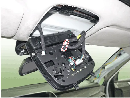
Check for continuity between the terminals. If the continuity is not
as specified, replace the panoramaroof switch.
|
Circuit Diagram Sunroof Roller blind Connector Pin Information Sunroof No Wire harness connector Panorama motor 1 Ground Ground 2 Open switch Open switch (SIG A) 3 ICU Enable ICU Enable 4 Tilt up switch Tilt up switch 5 Close switch LIN Bus 6 Battery (+) Battery (+) 7 Open alarm switch Open alarm switch 8 Vehicle speed Vehicle speed 9 - Config pin 10 - Close switch (SIG B) Roller blind No Wire harness connector Panorama motor 1 Ground Ground 2 Open switch Open switch (SIG A) 3 ICU Enable ICU Enable 4 - - 5 Close switch LIN Bus 6 Battery (+) Battery (+) 7 - - 8 - - 9 - Config pin 10 - Close switch (SIG B)
Repair procedures Replacement 1. Disconnect the negative (-) battery terminal. 2. Remove the roof trim assembly.
Other information:
Hyundai Palisade (LX2) 2020-2026 Service Manual: Description and operating principle
Description and Operation Wireless Power Charger System During ACC or IG ON, battery voltage is supplied to the wireless power charger system to transmit an output of 5 W to mobile phone. Mobile phones certified with the wireless charging standard WPC (Qi 1.
Hyundai Palisade (LX2) 2020-2026 Service Manual: Rear Evaporator Core
Repair procedures Replacement 1. Remove the rear heater & A/C unit. (Refer to Rear Heater - "Rear Heater Unit") 2. Loosen the mounting screws, remove the rear heater & A/C unit cover (A) and evaporator core (B).
Categories
- Manuals Home
- Hyundai Palisade Owners Manual
- Hyundai Palisade Service Manual
- Components and components location
- Emergency liftgate safety release
- Automatic Transaxle System (A8LF1)
- New on site
- Most important about car
