Hyundai Palisade (LX2): Lubrication System / Oil Level Gauge & Pipe
Repair procedures
| Removal and Installation |
| 1. |
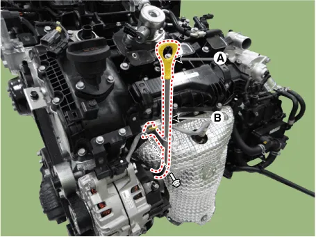
Remove the oil level gauge (A) and the oil level gauge rod (B).
|

| 2. |
Install in the reverse order of removal.
|
Repair procedures Removal and Installation • Be careful not to damage the parts located under the vehicle (floor under cover, fuel filter, fuel tank and canister) when raising the vehicle using the lift.
Other information:
Hyundai Palisade (LX2) 2020-2026 Service Manual: Description and operating principle
Description and Operation Wireless Power Charger System During ACC or IG ON, battery voltage is supplied to the wireless power charger system to transmit an output of 5 W to mobile phone. Mobile phones certified with the wireless charging standard WPC (Qi 1.
Hyundai Palisade (LX2) 2020-2026 Service Manual: Power Mosfet (DATC)
Repair procedures Inspection 1. Turn the ignition switch ON. 2. Manually operate the control switch and measure the voltage of the blower motor. 3. Select the control switch to raise the voltage until high speed.
Categories
- Manuals Home
- Hyundai Palisade Owners Manual
- Hyundai Palisade Service Manual
- Rain Sensor
- Repair procedures
- Removing and Storing the Spare Tire
- New on site
- Most important about car
