Hyundai Palisade (LX2): Lighting System / Turn Signal Lamp
Repair procedures
| Removal |
|

| 1. |
Disconnect the negative (-) battery terminal.
|
| 2. |
Remove the front door trim.
(Refer to Body - "Front Door Trim")
|
| 3. |
Remove the outside rear view mirror cover (A).
|

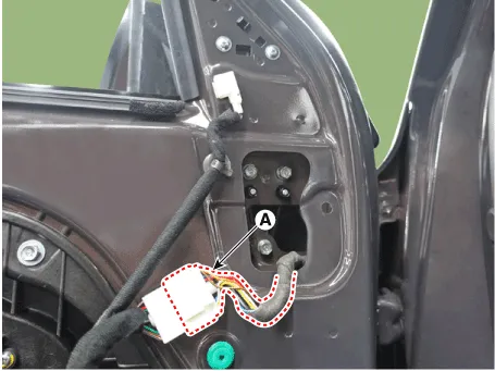
| 4. |
Disconnect the rear view mirror connector (A).
|
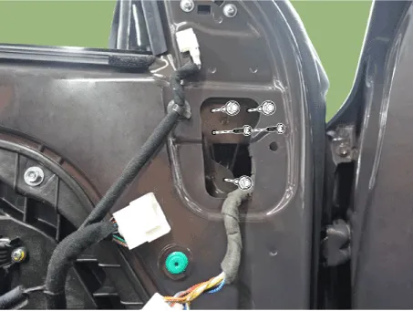
| 5. |
Loosen the mounting nuts and then remove the outside rear view mirror.
|
| 1. |
Disconnect the negative (-) battery terminal.
|
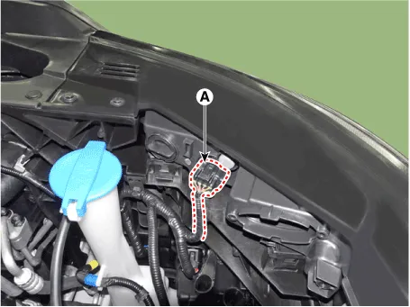
| 2. |
Remove the DRL connector (A).
|
| 3. |
Remove the DRL after loosening the mounting bolts.
|

| 1. |
Disconnect the negative (-) battery terminal.
|
| 2. |
Remove the rear combination lamp.
(Refer to Lighting System - "Rear Combination Lamp")
|
| Installation |
| 1. |
Install the outside mirror assembly and then connect the connector.
|
| 2. |
Connect the negative (-) battery terminal.
|
| 1. |
Install the DRL.
|
| 2. |
Connect the DRL connector.
|
| 3. |
Connect the negative (-) battery terminal.
|
| 1. |
Install the rear combination lamp.
|
| 2. |
Connect the negative (-) battery terminal.
|
Repair procedures Removal Head lamps become very hot during use; do not touch them or any attaching hardware immediately after they have been turned off.
Repair procedures Removal Room lamp 1. Disconnect the negative (-) battery terminal. 2. Detach the lamp lens (A) from the room lamp with a flat-tip screwdriver.
Other information:
Hyundai Palisade (LX2) 2020-2026 Service Manual: Heater Core
Repair procedures Replacement 1. Disconnect the negative (-) battery terminal. 2. Remove the heater and blower assembly. (Refer to Heater - "Heater Unit") 3.
Hyundai Palisade (LX2) 2020-2026 Service Manual: Repair procedures
Replacement 1. Disconnect the negative (-) battery terminal. 2. Remove the luggage side trim (Refer to Body - "Luggage Side Trim ") 3. Separate the rear mode actuator connector (A), loosen the mounting screws and remove the rear mode ac
Categories
- Manuals Home
- Hyundai Palisade Owners Manual
- Hyundai Palisade Service Manual
- Resetting the Driver's Seat Memory System
- Convenient Features of Your Vehicle
- Removing and Storing the Spare Tire
- New on site
- Most important about car
