Hyundai Palisade (LX2): Driveshaft Assembly / TJ Joint
Components and components location
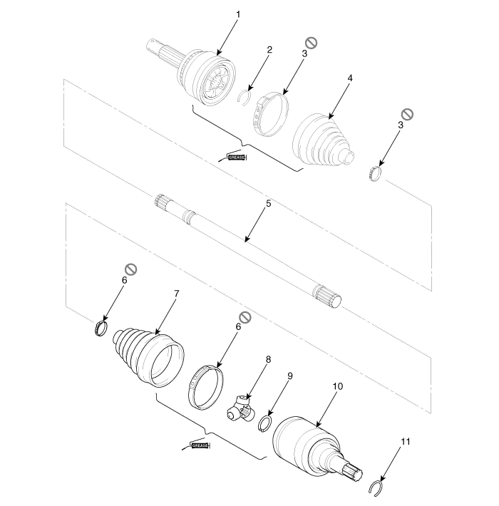
| Components |
| [LH] |
|
1. BJ assembly 2. BJ circlip 3. BJ boot band 4. BJ boot |
5. Shaft 6. TJ boot band 7. TJ boot 8. Spider assembly |
9. Retainer ring 10. TJ housing 11. Housing circlip |
| [RH] |
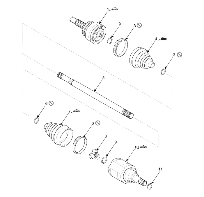
| 1. BJ assembly 2. BJ circlip 3. BJ boot band 4. BJ boot |
5. Shaft 6. TJ boot band 7. TJ boot 8. Spider assembly |
9. Clip 10. TJ Case 11. Clip 12. Housing circlip |
Repair procedures
| Removal |
|

| 1. |
Remove the Front Driveshaft.
(Refer to Driveshaft Assembly - "Front Driveshaft")
|
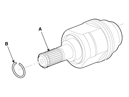
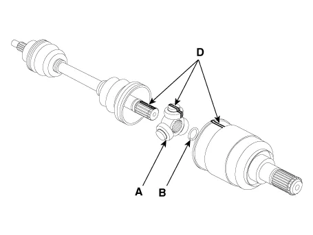
| 2. |
Remove the housing circlip (B) from the driveshaft spline (A).
|
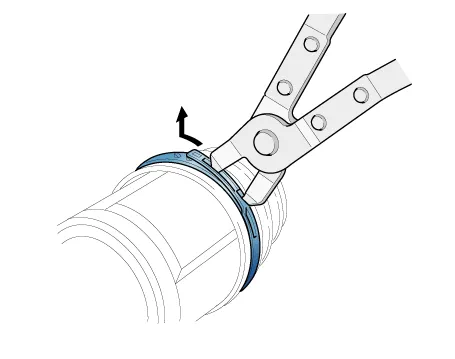
| 3. |
Remove both boot bands from the TJ housing.
|
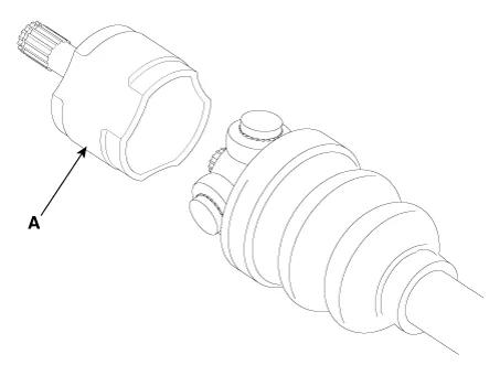
| 4. |
Remove the TJ housing (A).
|

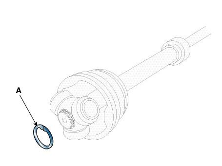
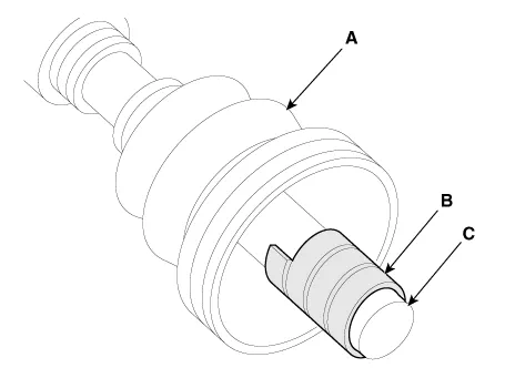
| 5. |
Remove the retainer ring (A) from the shaft.
|
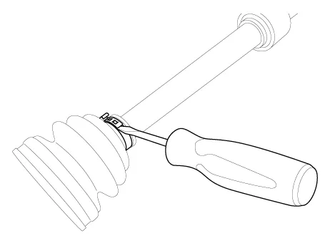
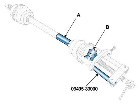
| 6. |
Remove the spider assembly (B) from the driveshaft (A) using the special
tool (09495-33000).
|
| 7. |
Clean the spider assembly.
|
| 8. |
Remove the TJ boot (A).
|

| Inspection |
| 1. |
Check the spider assembly for roller rotation, wear or corrosion.
|
| 2. |
Check the groove inside the joint case for wear or corrosion
|
| 3. |
Check the TJ boots for damage and deterioration.
|
| Installation |
| 1. |
Wrap tape around the driveshaft spline (TJ) to prevent damage to the
boot.
|
| 2. |
Install the TJ boot band and then TJ boot.
|
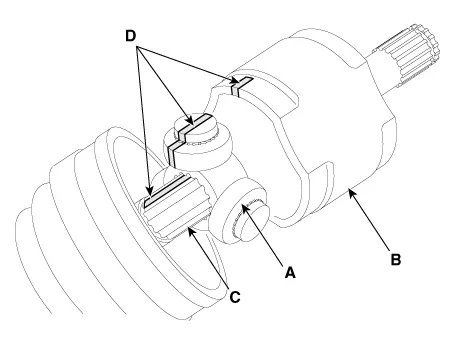
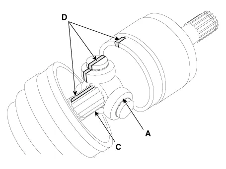
| 3. |
Using the alignment marks (D) made during disassembly as a guide, install
the spider assembly (A) and snap ring (B) on the driveshaft splines
(C).
|
| 4. |
Add specified grease to the joint boot as much as it was wiped away
at inspection.
|
| 5. |
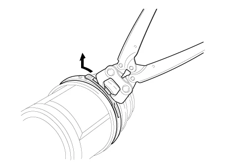
Install the both boot band.
|
| 6. |
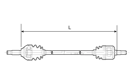
To control the air in the TJ boot, keep the specified distance between
the boot bands when they are tightened.
|
|||||||||||
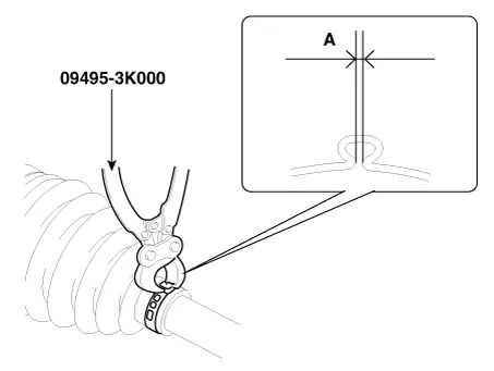
| 7. |
Using the SST(09495-3K000), secure the TJ boot bands.
|
| 8. |
Install the front driveshaft.
(Refer to Driveshaft Assembly - “Front Driveshaft”)
|
| 9. |
Check the front alignment.
(Refer to Suspension System - "Front Alignment")
|
Components and components location Components 1. Front driveshaft (LH) 2. Inner shaft bearing bracket 3. Front driveshaft (RH)
Components and components location Components [LH] 1. BJ assembly 2. BJ circlip 3. BJ boot band 4.
Other information:
Hyundai Palisade (LX2) 2020-2026 Service Manual: Cluster Ionizer
Description and operation Description The cluster ionizer makes disinfection and decomposition of bad smell from the air-conditioner or inflow air. And it cleans the inside air of a vehicle. When the ignition switch is ON, the ionizer runs "CLEAN" mode and then "ION" mode, switching between both modes.
Hyundai Palisade (LX2) 2020-2026 Service Manual: Auto Defogging Actuator
Description and operation Description The auto defogging sensor is installed on the front window glass. The sensor judges and sends signal if moisture occurs to blow out wind for defogging. The air conditioner control module receives a signal from the sensor and restrains moisture and eliminates defog by the intake actuato
Categories
- Manuals Home
- Hyundai Palisade Owners Manual
- Hyundai Palisade Service Manual
- Automatic Transaxle Fluid (ATF)
- How to reset the power liftgate
- Rear Heater Unit
- New on site
- Most important about car
