Hyundai Palisade (LX2): Driveshaft Assembly / BJ Boot
Components and components location
| Components |
| [LH] |
|
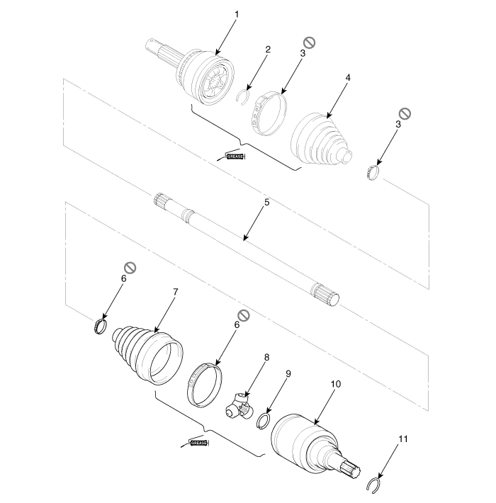
1. BJ assembly 2. BJ circlip 3. BJ boot band 4. BJ boot |
5. Shaft 6. TJ boot band 7. TJ boot 8. Spider assembly |
9. Retainer ring 10. TJ housing 11. Housing circlip |
| [RH] |
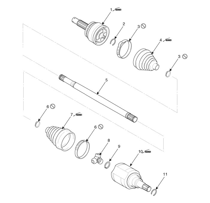
| 1. BJ assembly 2. BJ circlip 3. BJ boot band 4. BJ boot |
5. Shaft 6. TJ boot band 7. TJ boot 8. Spider assembly |
9. Retainer ring 10. TJ Housing 11. Housing circlip |
Components and components location Components [LH] 1. BJ assembly 2. BJ circlip 3. BJ boot band 4.
Other information:
Hyundai Palisade (LX2) 2020-2026 Service Manual: Special service tools
Special Service Tools Tool Name / Number Illustration Description LKA Compensator (09890-3V100) Used for compensating front view camera unit Tolerance Compensation Plate for Surround View Monitoring (09957-CM100)
Hyundai Palisade (LX2) 2020-2026 Service Manual: Rear Corner Safety ON/OFF Switch
Components and components location Circuit Diagram Repair procedures Inspection 1. Disconnect the negative (-) battery terminal. 2. Remove the crash pad lower panel. (Refer to Body - "Crashpad Lower Panel") 3.
Categories
- Manuals Home
- Hyundai Palisade Owners Manual
- Hyundai Palisade Service Manual
- Body Electrical System
- Components and components location
- General Tightening Torque Table
- New on site
- Most important about car

Copyright © 2026 www.hpalisadelx.com - 0.0101