Hyundai Palisade (LX2): Surround View Monitor (SVM) / Surround View Monitor (SVM) Unit
Components and components location
| Components |

|
No |
Connector A |
|
1 |
ACC |
|
2 |
LED |
|
3 |
EXT Ground |
|
4 |
Y Shield |
|
5 |
- |
|
6 |
C-CAN Low |
|
7 |
Y Video ground |
|
8 |
- |
|
9 |
- |
|
10 |
Rear camera power |
|
11 |
Left camera power |
|
12 |
Right camera power |
|
13 |
Ignition |
|
14 |
AVM switch |
|
15 |
- |
|
16 |
C Shield |
|
17 |
- |
|
18 |
C- CAN High |
|
19 |
C video ground |
|
20 |
C video output |
|
21 |
- |
|
22 |
- |
|
23 |
Left camera ground |
|
24 |
Right camera ground |

Repair procedures
| Removal |
| 1. |
Disconnect the negative (-) battery terminal.
|
| 2. |
Remove the carash pad lower panel.
(Refer to Body - "Crash Pad Lower Panel")
|
| 3. |
Disconnect the SVM unit connector.
|
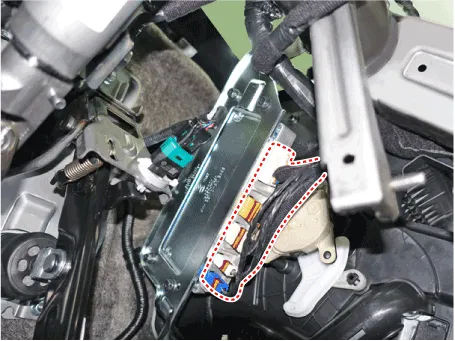
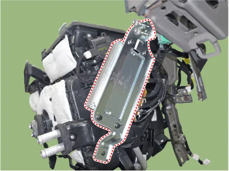
| 4. |
Remove the SVM unit after loosening the mounting bolts and screw.
|
| Installation |
| 1. |
Install the AVN head unit after connecting the AVN head unit connectors
and cable.
|
| 2. |
Install the crash pad lower panel.
|
| 3. |
Connect the negative (-) battery terminal.
|

| Inspection |
| How to Check the AVN Head Unit When Replacing It (Variant Coding) |
The following process describes the GDS based input method only.
|

| 1. |
Check the options installed on the vehicle before proceeding to the
AVN head unit variant coding.
|
| 2. |
Select a vehicle and then select "variant coding", an additional function
of the AVN head unit.
|
| 3. |
Set up the options installed on vehicles.
|


| 4. |
Follow the guidance of on-screen information and stand by. Wait until
it is completely saved and then exit.
|
Troubleshooting 1) After replacing H/UNIT, always check that the system operates properly.
Components and components location Components [Ultra Optical Camera - RH/LH] [Ultra Optical Camera - Front] [Ultra Optical Camera - Rear] Repair procedures Removal • In case of bad quality or poor focus, be sure to check the camera lense surface condition and foreign materials.
Other information:
Hyundai Palisade (LX2) 2020-2026 Service Manual: General safety information and caution
General Safety Information and Caution 1. Be careful when driving the vehicle using the smart cruise control system as follows. (1) On curves or inclines/declines • The smart cruise control system may have limits to detect
Hyundai Palisade (LX2) 2020-2026 Service Manual: Rear Corner Radar Unit
Specifications Specifications [BCW, BCA] Items Blind-Spot Collision Warning (BCW) Blind-Spot Collision- Avoidance Assist (BCA) Rated voltage DC 12V Operating voltage 9V - 16V Operating speed 30 km/h
Categories
- Manuals Home
- Hyundai Palisade Owners Manual
- Hyundai Palisade Service Manual
- Automatic Transaxle System (A8LF1)
- Scheduled maintenance services
- Rear Heater Unit
- New on site
- Most important about car
