Hyundai Palisade (LX2): Smart Key System / Smart Key
Repair procedures
| Smart Key |
| 1. |
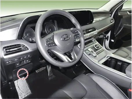
Connect the DLC cable of Diagnostic tool to the data link connector
(16 pins) in driver side crash pad lower panel, turn the power on Diagnostic
tool.
|
| 2. |
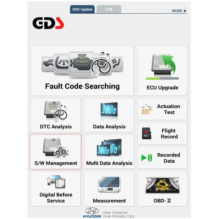
Select the 'S/W Management' and 'Car model'.
|
| 3. |
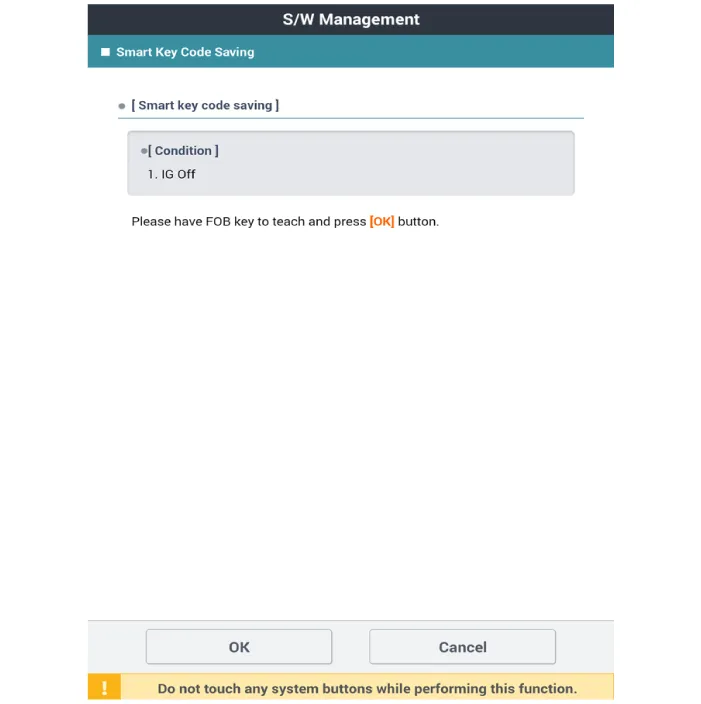
Select the 'Smart Key Unit' and 'Smart Key Code Saving'.
|

| 4. |
Follow the instructions on the screen.
|
Description The SMART KEY system is a system that allows the user to access and operate a vehicle in a very convenient way. To access the vehicle, no traditional key or remote control unit is needed.
Components and components location Components (1) Connector Pin Information No Connector A Connector B Connector C 1 - GND_ECU Front wiper relay (Low)_output 2 - PDW-F power_output ESCL (+)_output 3 GND_Power ESCL (-)_output Start relay_output 4 PDW-R_Power_Output Front wiper high relay_output IGN1 relay_output 5 - PDW-R WIND_output Immobilizer antenna power_output 6 Rear washer switch_input - Immobilizer antenna ground_output 7 LIN4 (Rear seat remind) - - 8 P_CAN (Low) Rear view switch_input Interior1 antenna (+)_output 9 P_CAN (High) - Driver outside handle antenna(+)_output 10 - Wheel speed sensor_input - 11 B_CAN (Low) - Passenger outside handle antenna(+)_output 12 B_CAN (High) 3rd line sheet belt indicator RH_output - 13 SSB switch_input Passenger seat belt indicator_output Trunk interior antenna3(+)_output 14 Driver handle antenna switch_input Rear center seat belt indicator_output Immobilizer K-Line 15 P position_input (AT) - Bumper antenna (+)_output - 16 Fog switch_input LF searching_output Interior antenna2(+)_output 17 Light switch_input Auto light sensor signal_input IGN2_input 18 Front wiper INT volume switch_input Auto light sensor power_output IGN1_input 19 Multifunction switch_input ATM solenoid_output IGN2 relay_output 20 Right side mirror unfolding switch_oupout Puddle pocket lamp_output Battery_power 21 Right side mirror heater_output - Brake switch_input 22 Front washer switch_input SSB ring illumination_output Start feedback_input 23 Front wiper low switch_Input piezo buzzer_output Security indicator_output 24 LIN1 (PDW) SSB symbol illumination_output Interior1 (-)_output 25 LIN2 (Safety ECU) 3rd line sheet belt indicator_output Driver outside handle antenna (-)_output 26 LIN3 (Rain sensor) Wiper power relay_output - 27 PDW power_input Rear seat belt indicator RH_output Passenger outside handle antenna (-)_output 28 PDW_input Rear seat belt indicator LH_output ESCL COM 29 SSB switch1_input 3rd line sheet belt indicator LH_output Trunk Interior antenna3(-)_output 30 ESCL unlock_input Rear wiper relay_output ESCL Enable_output 31 Passenger outside handle switch_input Auto light sensor ground_output Bumper antenna (-)_output 32 PDW switch_input Wiper parking switch_input Interior antenna2 (-)_output 33 Sun roof Status_input ACC_input 34 Head lamp switch_input Mirror power_input 35 Front wiper switch_input ACC relay_output 36 Rear wiper switch_input ECU battery (+) 37 Mirror folding RH_output 38 Mirror RH VT_output
Other information:
Hyundai Palisade (LX2) 2020-2026 Service Manual: Wireless Power Charging Unit
Components and positions Components Circuit diagram Circuit Diagram Repair procedures Removal Handling wireless charging system parts by wet hands may cause electric shock.
Hyundai Palisade (LX2) 2020-2026 Service Manual: Components and components location
Categories
- Manuals Home
- Hyundai Palisade Owners Manual
- Hyundai Palisade Service Manual
- Rear Heater Unit
- How to reset the power liftgate
- Electrochromatic Mirror (ECM) with homelink system
- New on site
- Most important about car
