Hyundai Palisade (LX2): Rear Suspension System / Rear Shock Absorber
Components and components location
| Components |
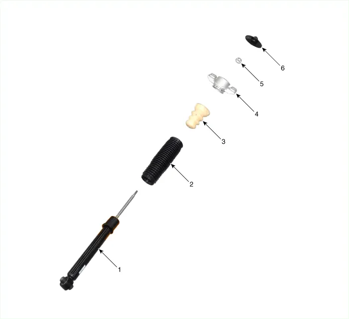
| 1. Rear shock absorber 2. Dust cover 3. Bumper rubber |
4. Insulator assembly 5. Lock nut 6. Insulator cap |
Repair procedures
| Removal |
| 1. |
Loosen the wheel nuts slightly.
Raise the vehicle, and make sure it is securely supported.
|
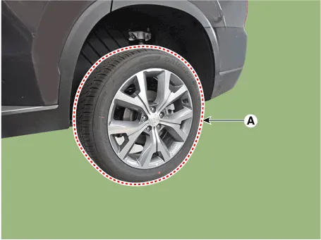
| 2. |
Remove the rear wheel and tire (A) from rear hub.
|

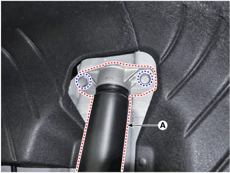
| 3. |
Remove the rear shock absorber (A) from the body by loosening the bolt.
|
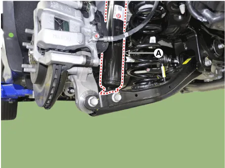
| 4. |
Loosen the bolt & nut and then remove the rear shock absorber (A) from
the lower arm.
|
| Disassembly |
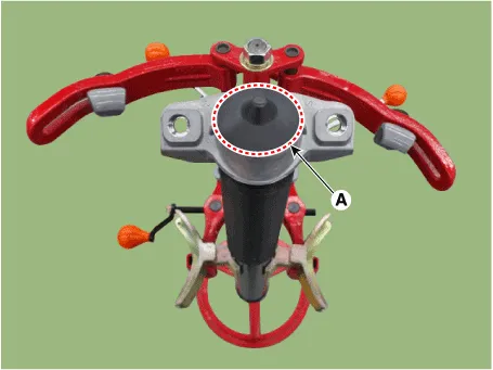
| 1. |
Remove the lock nut cover (A).
|
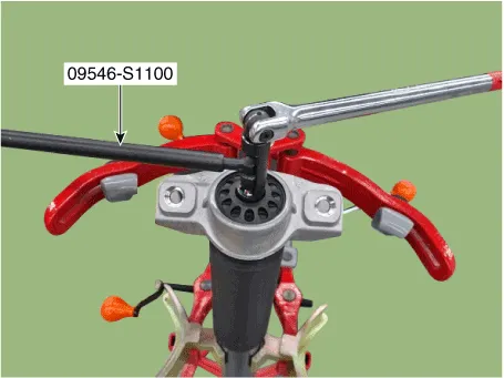
| 2. |
Using the special tool (09546-S1100), install the self locking nut.
|

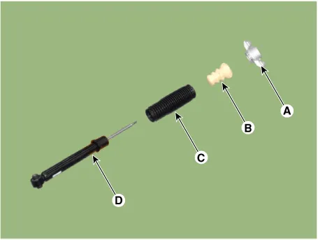
| 3. |
Separate the Insulator assembly (A), bumper rubber (B), dust cover (C),
shock absorber (D).
|
| Inspection |
| 1. |
Check the rubber parts for damage or deterioration.
|
| 2. |
Check the shock absorber for abnormal resistance or unusual sounds.
|
| Disposal |
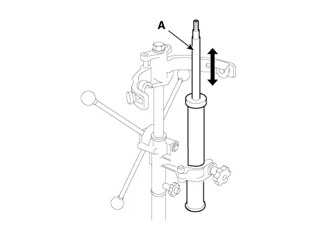
| 1. |
Fully extend the shock absorber rod.
|
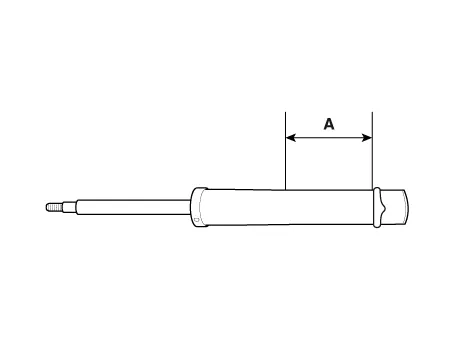
| 2. |
Drill a hole to remove gas from the cylinder.
|

| Reassembly |
| 1. |
To reassembly, reverse the disassembly procedure.
|
| 2. |
Using SST(09546-3X100), install the lock nut.
|

| 3. |
Install the lock nut cover (A).
|

| Installation |
| 1. |
Install in the reverse order of removal.
|
Components 2WD 1. Rear shock absorber 2. Rear lower arm 3. Rear stabilizer bar 4. Rear cross member 5.
Repair procedures Removal 1. Loosen the wheel nuts slightly. Raise the vehicle, and make sure it is securely supported.
Other information:
Hyundai Palisade (LX2) 2020-2026 Service Manual: Rear Blower Motor
Repair procedures Replacement 1. Disconnect the negative (-) battery terminal. 2. Remove the luggage side trim (Refer to Body - "Luggage Side Trim ") 3. Separate the rear blower motor connector (A), loosen the mounting screws and remov
Hyundai Palisade (LX2) 2020-2026 Service Manual: Smart Cruise Control (SCC) Switch
Components and components location Components 1. Remote control switch (Audio swtich) 2. Remote control switch (Cruise control switch) Schematic diagrams Circuit Diagram Trip + SCC Repair procedures Removal 1.
Categories
- Manuals Home
- Hyundai Palisade Owners Manual
- Hyundai Palisade Service Manual
- Body (Interior and Exterior)
- Body Electrical System
- Resetting the Driver's Seat Memory System
- New on site
- Most important about car
