Hyundai Palisade (LX2): Engine Control System / CVVT Oil Temperature Sensor (OTS)
Description and operation
| Description |

Specifications
| Specification |
|
Temperature |
Resistance (kΩ) |
|
|
°C |
°F |
|
|
-40 |
-40 |
41.74 - 54.54 |
|
-20 |
-4 |
14.13 - 16.83 |
|
0 |
32 |
5.28 - 6.3 |
|
25 |
77 |
1.88 - 2.14 |
|
80 |
176 |
0.31 - 0.33 |
|
140 |
284 |
0.07 - 0.08 |
Schematic diagrams
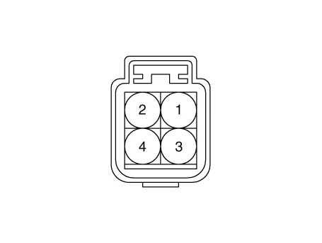
| Circuit Diagram |
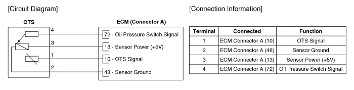
Repair procedures
| Inspection |
| 1. |
Switch "OFF" the ignition.
|
| 2. |
Disconnect the OTS connector.
|
| 3. |
Remove the OTS.
|
| 4. |
After immersing the thermistor of the sensor into engine coolant, measure
resistance between the OTS terminals 1 and 2.
|
| 5. |
Check that the resistance is within the specification.
|
|||||||||||||||||||||||
| Removal |
| 1. |
Refer to Engine Mechanical System - "Oil Pressure Sensor"
|
| Installation |
| 1. |
Refer to Engine Mechanical System - "Oil Pressure Sensor"
|
Description and operation Description Installed on the delivery pipe, the Rail Pressure Sensor (RPS) measures the instantaneous fuel pressure in the delivery pipe.
Description and operation Description Continuous Variable Valve Timing (CVVT) system advances or retards the valve timing of the intake and exhaust valve in accordance with the ECM control signal which is calculated by the engine speed and load.
Other information:
Hyundai Palisade (LX2) 2020-2026 Service Manual: Climate Control Air Filter
Description and operation Description The climate control air filter is located in the blower unit. It eliminates foreign materials and odor. The particle filter performs a role as an odor filter as well as a conventional dust filter to ensure comfortable interior environment.
Hyundai Palisade (LX2) 2020-2026 Service Manual: Description and operation
Description The cruise control system is engaged by the cruise "ON/OFF" main switch located on right of steering wheel column. The system has the capability to cruise, coast, accelerate and resume speed. It also has a safety interrupt, engaged upon depressing brake or shifting select lever.
Categories
- Manuals Home
- Hyundai Palisade Owners Manual
- Hyundai Palisade Service Manual
- Body (Interior and Exterior)
- Removing and Storing the Spare Tire
- How to reset the power liftgate
- New on site
- Most important about car
