Hyundai Palisade (LX2): Cylinder Block / Crankshaft
Repair procedures
| Disassembly |
|
|
|
| 1. |
Remove the engine assembly from the vehicle.
(Refer to Engine and Transaxle Assembly - "Engine And Transaxle Assembly")
|
| 2. |
Remove the transaxle assembly from the engine assembly.
(Refer to Automatic Transaxle System - "Automatic Transaxle")
|
| 3. |
Remove the drive plate and adapter plate.
(Refer to Cylinder Block - "Drive Plate")
|
| 4. |
Remove the rear oil seal case.
(Refer to Cylinder Block - "Rear Oil Seal")
|
| 5. |
Install the engine assembly to engine stand for disassembly.
|
| 6. |
Remove the surge tank.
(Refer to Intake and Exhaust System - "Surge Tank")
|
| 7. |
Remove the intake manifold.
(Refer to Intake and Exhaust System - "Intake Manifold")
|
| 8. |
Remove the exhaust manifold.
(Refer to Intake and Exhaust System - "Exhaust Manifold")
|
| 9. |
Remove the timing chain.
(Refer to Timing System - "Timing Chain")
|
| 10. |
Remove the water temperature control assembly.
(Refer to Cooling System - "Water Temperature Control Assembly")
|
| 11. |
Remove the cylinder head assembly.
(Refer to Cylinder Head Assembly - "Cylinder Head")
|
| 12. |
Remove the lower oil pan and upper oil pan.
(Refer to Lubrication System - "Oil Pan")
|
| 13. |
Remove the oil pump.
(Refer to Lubrication System - "Oil Pump")
|
| 14. |
Remove the oil filter body.
(Refer to Lubrication System - "Oil filter body")
|
| 15. |
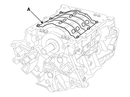
Remove the baffle plate (A).
|
| 16. |
Check the connecting rod end play.
(Refer to Cylinder Block - "Piston and Connecting Rod")
|
| 17. |
Check the connecting rod cap oil clearance.
(Refer to Cylinder Block - "Piston and Connecting Rod")
|
| 18. |
Remove the piston and connecting rod assemblies.
(Refer to Cylinder Block - "Piston and Connecting Rod")
|
| 19. |
Remove the crankshaft main bearing cap and check oil clearance.
|
| 20. |
Check the crankshaft end play.
|
| 21. |
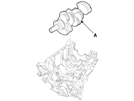
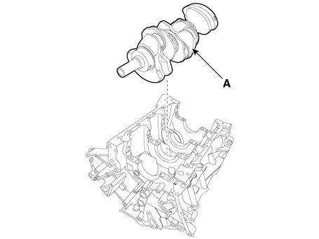
Remove the crankshaft. Lift the crankshaft (A) out of engine, being
careful not to damage journals.
|
| Inspection |
| 1. |
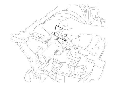
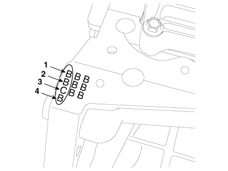
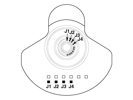
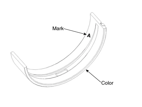
Check the crankshaft bearing oil clearance.
|
|||||||||||||||||||||||||||||||||||||||||||||||||||||||||||||||||||||||||||||||||||||||||||||||||||||||||
| 2. |
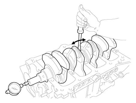
Check crankshaft end play.
Using a dial indicator, measure the thrust clearance while prying the
crankshaft back and forth with a screwdriver.
If the end play is greater than maximum, replace the thrust bearings
as a set.
|
| 3. |
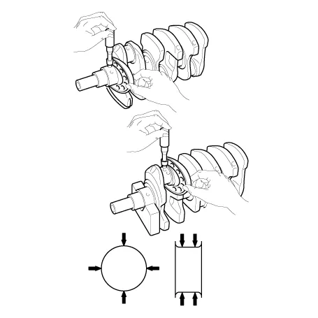
Inspect main journals and crank pins
Using a micrometer, measure the diameter of each main journal and crank
pin.
|
| Reassembly |
|
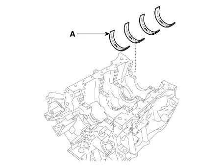
| 1. |
Install the main bearings.
|
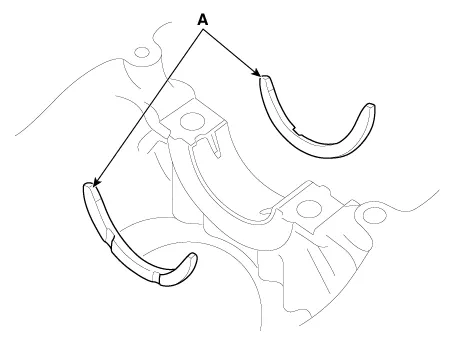
| 2. |
Install the thrust bearings.
Install the 2 thrust bearings (A) under the No. 3 journal position of
the cylinder block with the oil grooves facing outward.
|
| 3. |
Place the crankshaft (A) on the cylinder block.
|
| 4. |
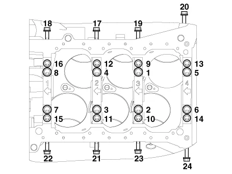
Place the main bearing caps on cylinder block.
|
| 5. |
Install the main bearing cap bolts.
|
| 6. |
Check crankshaft end play.
|
| 7. |
Install the piston and connecting rod assemblies.
(Refer to Cylinder Block - "Piston and Connecting Rod")
|
| 8. |
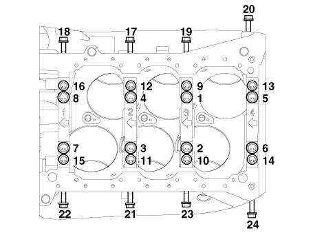
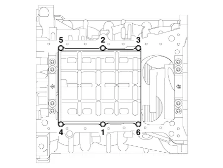
Install the baffle plate.
Install and uniformly tighten the baffle plate bolts, in several passes,
in the sequence shown.
|
| 9. |
Assemble the remaining parts in the reverse order of disassembly.
|
Repair procedures Disassembly • Be careful not to damage the parts located under the vehicle (floor under cover, fuel filter, fuel tank and canister) when raising the vehicle using the lift.
Repair procedures Disassembly • Be careful not to damage the parts located under the vehicle (floor under cover, fuel filter, fuel tank and canister) when raising the vehicle using the lift.
Other information:
Hyundai Palisade (LX2) 2020-2026 Service Manual: Specification
Hyundai Palisade (LX2) 2020-2026 Service Manual: Description and operation
Description Blind-Spot Radar is a system that measures the relative speed and distance from the following vehicles by using two electromagnetic wave radar sensors attached to the rear bumper, and detects any vehicle within the blind spot zone and gives off alarm (visual and auditory).
Categories
- Manuals Home
- Hyundai Palisade Owners Manual
- Hyundai Palisade Service Manual
- Lift and Support Points
- Power Outlet
- Engine Mechanical System
- New on site
- Most important about car


