Hyundai Palisade (LX2): Panorama Sunroof / Panorama Sunroof Switch
Repair procedures
| Inspection |
| 1. |
Disconnect the negative (-) battery terminal.
|
| 2. |
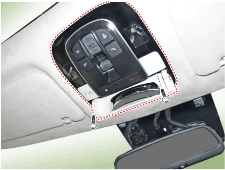
Open the sunglass case cover from the overhead console then remove screws
(2EA).
|
| 3. |
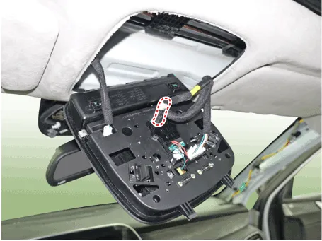
Check for continuity between the terminals. If the continuity is not
as specified, replace the panoramaroof switch.
|
Circuit Diagram Sunroof Roller blind Connector Pin Information Sunroof No Wire harness connector Panorama motor 1 Ground Ground 2 Open switch Open switch (SIG A) 3 ICU Enable ICU Enable 4 Tilt up switch Tilt up switch 5 Close switch LIN Bus 6 Battery (+) Battery (+) 7 Open alarm switch Open alarm switch 8 Vehicle speed Vehicle speed 9 - Config pin 10 - Close switch (SIG B) Roller blind No Wire harness connector Panorama motor 1 Ground Ground 2 Open switch Open switch (SIG A) 3 ICU Enable ICU Enable 4 - - 5 Close switch LIN Bus 6 Battery (+) Battery (+) 7 - - 8 - - 9 - Config pin 10 - Close switch (SIG B)
Repair procedures Replacement 1. Disconnect the negative (-) battery terminal. 2. Remove the roof trim assembly.
Other information:
Hyundai Palisade (LX2) 2020-2026 Service Manual: Components and positions
Hyundai Palisade (LX2) 2020-2026 Service Manual: Description and operation
Description The smart cruise control system allows a driver to program the vehicle to control the speed and following distance by detecting the vehicle ahead without depressing the brake pedal or the accelerator pedal. 1.
Categories
- Manuals Home
- Hyundai Palisade Owners Manual
- Hyundai Palisade Service Manual
- Emergency liftgate safety release
- General Tightening Torque Table
- Components and components location
- New on site
- Most important about car
