Hyundai Palisade (LX2): Front Suspension System / Front Strut Assembly
Hyundai Palisade (LX2) 2020-2026 Service Manual / Suspension System / Front Suspension System / Front Strut Assembly
Components and components location
| Components |
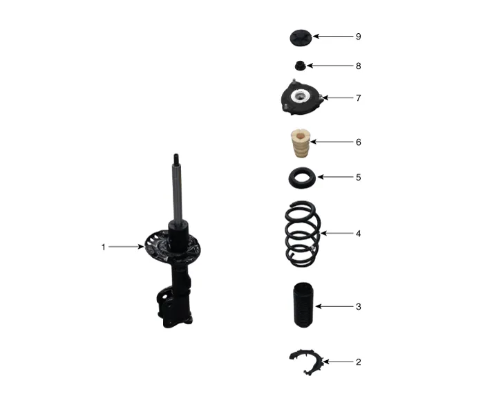
| 1. Strut assembly 2. Spring lower pad 3. Dust cover 4. Coil spring 5. Spring upper pad |
6. Bumper rubber 7. Insulator assembly & sturt bearing 8. Lock nut 9. Insulator cap |
Repair procedures
| Removal |
| 1. |
Loosen the wheel nuts slightly.
Raise the vehicle, and make sure it is securely supported.
|
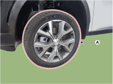
| 2. |
Remove the front wheel and tire (A) from the front hub.
|

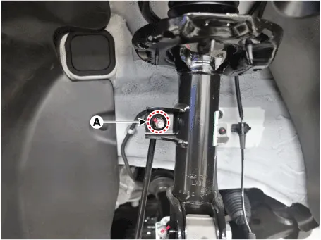
| 3. |
Disconnect the stabilizer link with the front strut assembly after loosening
the nut (A).
|

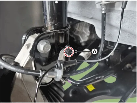
| 4. |
Loosen the mounting bolt (A) and then remove the brake hose bracket
from the strut assembly.
|
| 5. |
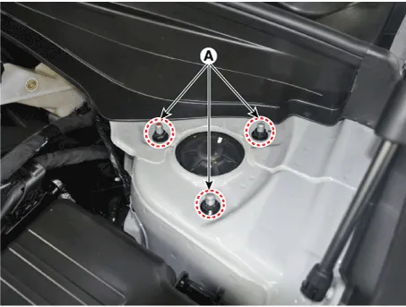
Loosen the upper strut mounting nuts (A).
|
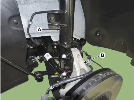
| 6. |
Remove the front strut assembly (A) from the front axle (B) by loosening
the bolts & nuts.
|
| Disassembly |
|

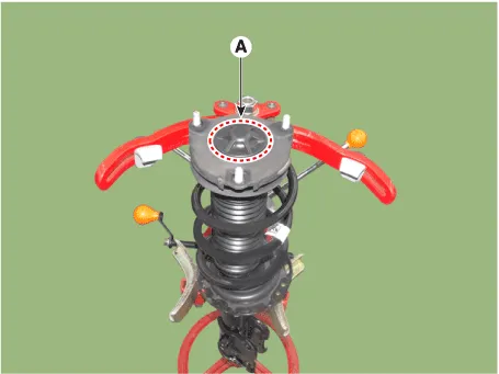
| 1. |
Remove the insulator cap (A).
|
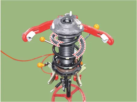
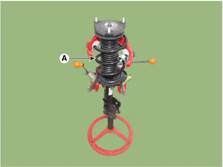
| 2. |
Using the spring compressor, compress the coil spring (A).
|
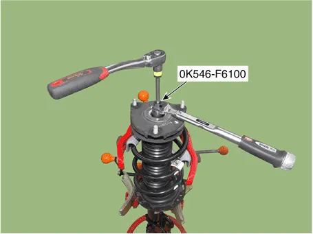
| 3. |
Using SST (0K546-F6100), loosen the self locking nut.
|
| 4. |
Remove the insulator, spring pad, coil spring and dust cover from the
strut assembly.
|
| Inspection |
| 1. |
Check the strut insulator for wear or damage.
|
| 2. |
Check rubber parts for damage or deterioration.
|
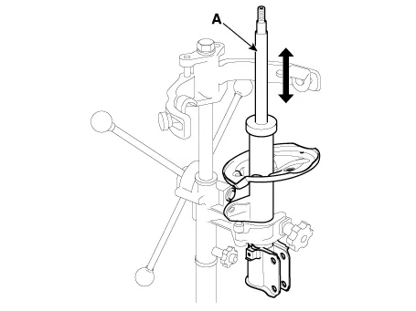
| 3. |
Compress and extend the piston rod (A) and check that there is no abnormal
resistance or unusual sound during operation.
|
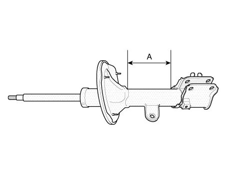
Disposal
| 1. |
Fully extend the piston rod.
|
| 2. |
Drill a hole on the A section to remove gas from the cylinder.
|

| Reassembly |
| 1. |
Install the insulator, spring pad, coil spring and dust cover from the
strut assembly.
|
| 2. |
Compress and extend the piston rod (A) and check that there is no abnormal
resistance or unusual sound during operation
|

| 3. |
Using the special tool (0K546-F6100), install the self locking nut.
|


| Installation |
| 1. |
Install in the reverse order of removal.
|
| 2. |
Check the alignment.
(Refer to Suspension System - "Alingment")
|
Components Location 1. Front axle assembly 2. Stabilizer bar 3. Steering gearbox 4. Sub frame 5. Front lower arm 6.
Repair procedures Removal 1. Loosen the wheel nuts slightly. Raise the vehicle, and make sure it is securely supported.
Other information:
Hyundai Palisade (LX2) 2020-2026 Service Manual: Special service tools
Hyundai Palisade (LX2) 2020-2026 Service Manual: Blower Motor
Repair procedures Inspection 1. Connect the battery voltage and check the blower motor rotation. 2. If the blower motor does not operate well, substitute with a known-good blower motor and check for proper operation.
Categories
- Manuals Home
- Hyundai Palisade Owners Manual
- Hyundai Palisade Service Manual
- Convenient Features of Your Vehicle
- Body Electrical System
- Rain Sensor
- New on site
- Most important about car

Copyright © 2026 www.hpalisadelx.com - 0.0147