Hyundai Palisade (LX2): Front Suspension System / Front Lower Arm
Hyundai Palisade (LX2) 2020-2026 Service Manual / Suspension System / Front Suspension System / Front Lower Arm
Repair procedures
| Removal |
| 1. |
Loosen the wheel nuts slightly.
Raise the vehicle, and make sure it is securely supported.
|
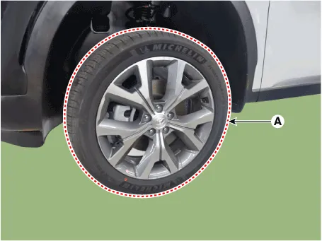
| 2. |
Remove the front wheel and tire (A) from the front hub.
|

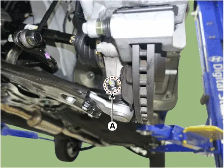
| 3. |
Remove the split pin and nut (A).
|

| 4. |
Remove the lower arm from the knuckle by using the SST (09568-4R100).
|

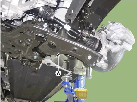
| 5. |
Remove the front lower arm (A) after loosening the bolts & nuts.
|
| Inspection |
| 1. |
Check the bushing for wear and deterioration.
|
| 2. |
Check the lower arm for bending or breakage.
|
| 3. |
Check the lower arm for deformation.
|
| 4. |
Check the all bolts and nuts.
|
| Replacement |
| 1. |
Loosen the wheel nuts slightly.
Raise the vehicle, and make sure it is securely supported.
|
| 2. |
Remove the front wheel and tire (A) from the front hub.
|


| 3. |
Remove the split pin and nut (A).
|
| 4. |
Remove the lower arm from the knuckle by using the SST (09568-4R100).
|
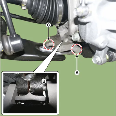
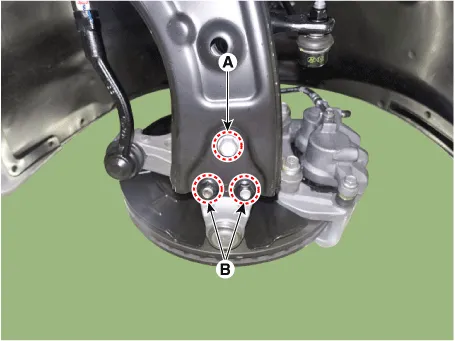
| 5. |
Remove the ball joint assembly after losening the bolt (A) and nut (B).
|
Components and components location Components 1. Strut assembly 2. Spring lower pad 3. Dust cover 4. Coil spring 5.
Repair procedures Removal 1. Turn the ignition switch OFF and disconnect the battery negative (-) cable. 2.
Other information:
Hyundai Palisade (LX2) 2020-2026 Service Manual: Heater & A/C Control Unit (Rear)
Components and components location Component Connector Pin Function Connector PIN No Pin Function Connector PIN No Pin Function A 1 Battery A 17 IGN2 2
Hyundai Palisade (LX2) 2020-2026 Service Manual: Description and operation
Categories
- Manuals Home
- Hyundai Palisade Owners Manual
- Hyundai Palisade Service Manual
- How to reset the power liftgate
- Electrochromatic Mirror (ECM) with homelink system
- Power Outlet
- New on site
- Most important about car

Copyright © 2026 www.hpalisadelx.com - 0.0193