
Hyundai Palisade (LX2): Floor Console / Floor Console Assembly
Components and components location
| Component Location |
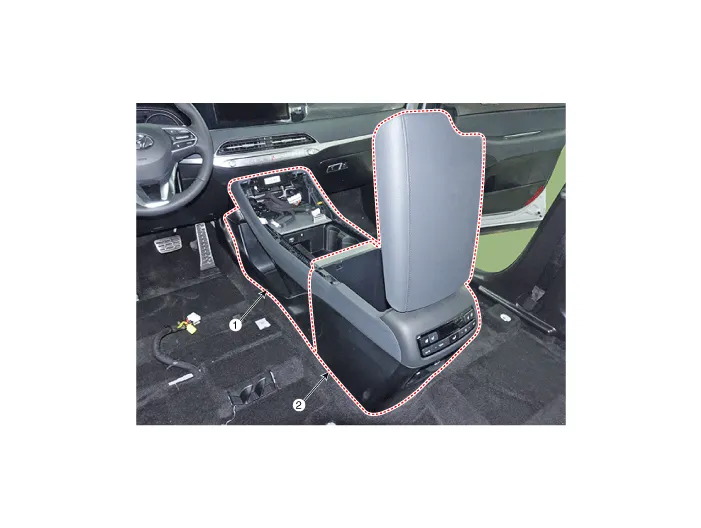
| 1. Front console assembly |
2. Rear console assembly |
Repair procedures
| Replacement |
|

|

| 1. |
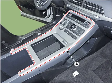
Using a flat-tip screwdriver or remover and remove the console upper
cover (A).
|
| 2. |
Press the lock pin and separate the Various connectors (A).
|

| 3. |
Loosen the mounting bolts and remove the rear console assembly (A).
|

| 4. |
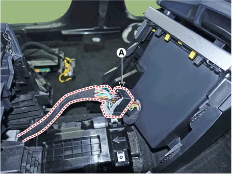
Press the lock pin and separate the rear console assembly connector
(A).
|
| 5. |
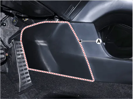
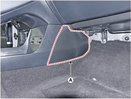
Using a remover and remove the console side cover (A).
[LH]
[RH]
|
| 6. |
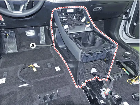
Loosen the mounting screws and remove the front console assembly (A).
|
| 7. |
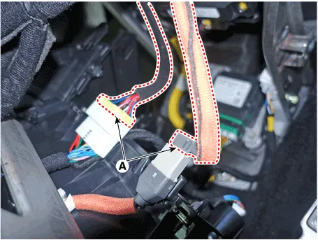
Press the lock pin and separate the connector (A).
|
| 8. |
To install, reverse removal procedure.
|

Components 1. Floor console rear mounting bracket 2. Rear console assembly 3. Console storage box 4. Front console assembly 5.
Components and components location Component Location 1. Rear console upper cover 2. Rear console under cover Repair procedures Replacement [Upper] • When removing with a flat-tip screwdriver or remover, wrap protective tape around the tools to prevent damage to components.
Other information:
Hyundai Palisade (LX2) 2020-2026 Service Manual: General safety information and caution
General Safety Information and Caution 1. Be careful when driving the vehicle using the smart cruise control system as follows. (1) On curves or inclines/declines • The smart cruise control system may have limits to detect
Hyundai Palisade (LX2) 2020-2026 Service Manual: Smart Cruise Control (SCC) Switch
Components and components location Components 1. Remote control switch (Audio swtich) 2. Remote control switch (Cruise control switch) Schematic diagrams Circuit Diagram Trip + SCC Repair procedures Removal 1.
Categories
- Manuals Home
- Hyundai Palisade Owners Manual
- Hyundai Palisade Service Manual
- Automatic Transaxle Fluid (ATF)
- Rain Sensor
- Electronic Child Safety Lock System
- New on site
- Most important about car
