Hyundai Palisade (LX2): Engine And Transaxle Assembly / Engine And Transaxle Assembly
Repair procedures
| Removal |
|

|

|

| 1. |
Disconnect the battery negative terminal.
|
| 2. |
Remove the engine cover.
(Refer to Engine and Transaxle Assembly - "Engine Cover")
|
| 3. |
Remove the air duct.
(Refer to Intake and Exhaust System - "Air Cleaner")
|
| 4. |
Disconnect the battery positive terminal.
|
| 5. |
Remove the air cleaner assembly.
(Refer to Intake and Exhaust System - "Air Cleaner")
|
| 6. |
Remove the battery and battery tray.
(Refer to Engine Electrical System - "Battery")
|
| 7. |
Remove the engine control module (ECM).
(Refer to Engine Control / Fuel System - "Engine Control Module (ECM)")
|
| 8. |
Remove the engine room under cover.
(Refer to Engine and Transaxle Assembly - "Engine Room Under Cover")
|
| 9. |
Drain the engine coolant.
(Refer to Cooling System - "Coolant")
|
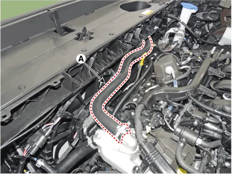
| 10. |
Disconnect the radiator upper hose (A).
|
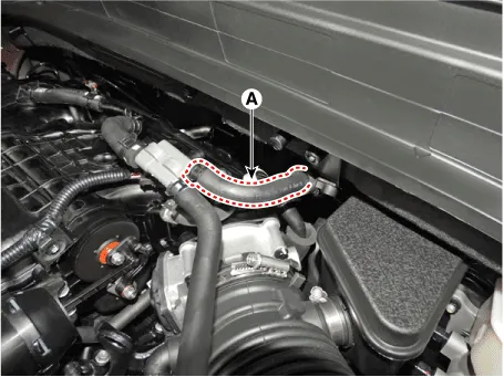
| 11. |
Disconnect the radiator lower hose (A).
|
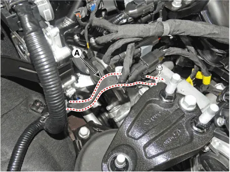
| 12. |
Disconnect the brake booster vacuum hose (A).
|
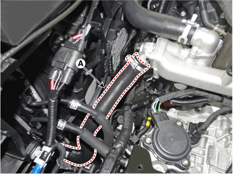
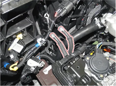
| 13. |
Disconnect the heater hoses (A).
|
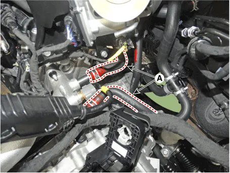
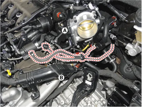
| 14. |
Disconnect the fuel hose (A) and the purge control solenoid valve (PCSV)
hose (B).
|
| 15. |
Recover the refrigerant and then remove the high pressure pipe and low
pressure pipe.
(Refer to Heating, Ventilation Air conditioning - "Compressor")
|
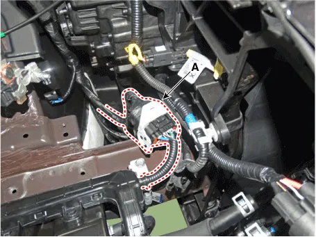
| 16. |
Remove the engine wiring connector and harness.
|
| 17. |
Disconnect the ATF cooler hoses (A).
|
| 18. |
Remove the roll rod bracket (A).
|
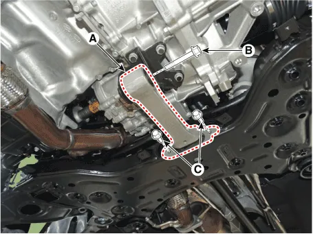
| 19. |
Remove the roll rod mounting support bracket (A).
|
| 20. |
Remove the sub frame.
(Refer to Suspension System - "Sub frame")
|
| 21. |
Remove the front muffler.
(Refer to Intake and Exhaust System - "Muffler")
|
| 22. |
Remove the propeller shaft. [AWD type]
(Refer to Driveshaft and Axle - "Propeller Shaft Assembly")
|
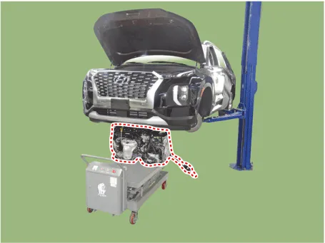
| 23. |
Support the engine and transaxle assembly on a lift table.
|
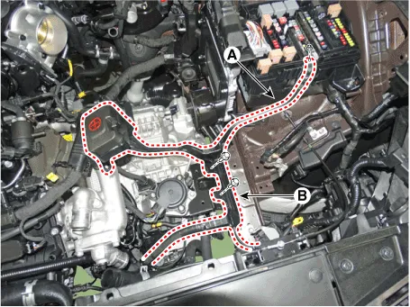
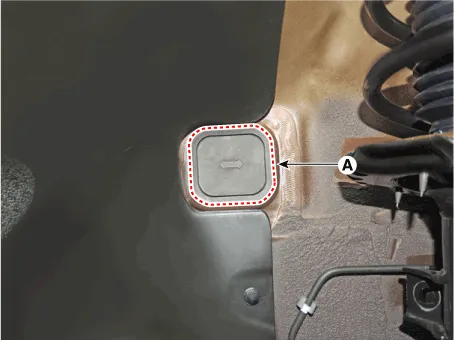
| 24. |
Disconnect the engine ground cable (A).
|
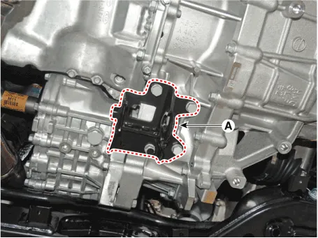
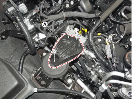
| 25. |
Remove the engine mounting support bracket (A).
|
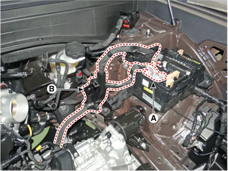
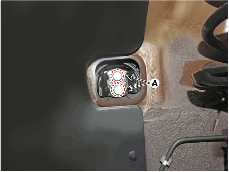
| 26. |
Disconnect the transaxle ground cable (A).
|

| 27. |
Remove the service cover (A).
|
| 28. |
Remove the transaxle support bracket mounting bolts (A).
|
| 29. |
Remove the engine and transaxle assembly by lifting vehicle.
|

| Installation |
| • |
Adjust a shift cable.
|
| • |
Refill engine with engine oil.
|
| • |
Refill a transaxle with fluid.
|
| • |
Refill a radiator and a reservoir tank with engine coolant.
|
| • |
Place a heater control knob on "HOT" position.
|
| • |
Clean battery posts and cable terminals and assemble.
|
| • |
Inspect for fuel leakage.
|
| – |
After assemble the fuel line, turn on the ignition switch (do not operate
the starter) so that the fuel pump runs for approximately two seconds
and fuel line pressurizes.
|
| – |
Repeat this operation two or three times, then check for fuel leakage
at any point in the fuel line.
|
| • |
Bleed air from the cooling system.
|
| – |
Start engine and let it run until it warms up. (until the radiator fan
operates 3 or 4 times.)
|
| – |
Turn Off the engine and let it cool down. Check the level in the radiator,
add coolant if needed. This will allow trapped air to be removed from
the cooling system.
|
| – |
Put radiator cap on tightly, then run the engine again and check for
leaks.
|
Components and components location Components 1. Transaxle mounting bracket 2. Roll rod bracket 3. Engine mounting support bracket 4.
Other information:
Hyundai Palisade (LX2) 2020-2026 Service Manual: Repair procedures
Inspection Tolerance Compensation Tolerance compensation compensates for the error margins of around view video that occur due to the installation tolerance when the four cameras that comprise the SVM system are installed. You must carry out tolerance compensation if you do any of the following.
Hyundai Palisade (LX2) 2020-2026 Service Manual: Surround View Monitor (SVM) Camera
Components and components location Components [Ultra Optical Camera - RH/LH] [Ultra Optical Camera - Front] [Ultra Optical Camera - Rear] Repair procedures Removal • In case of bad quality or poor
Categories
- Manuals Home
- Hyundai Palisade Owners Manual
- Hyundai Palisade Service Manual
- Troubleshooting
- Resetting the Driver's Seat Memory System
- General Tightening Torque Table
- New on site
- Most important about car
