Hyundai Palisade (LX2): Integrated Body Control Unit (IBU) / Description and operation
Hyundai Palisade (LX2) 2020-2026 Service Manual / Body Electrical System / Integrated Body Control Unit (IBU) / Description and operation
| Description |
Body Control Module Controls The Followings
| – |
Wiper & Washer Control
|
| – |
Defroster Control
|
| – |
Driving Control
|
| – |
Tailgate Control
|
| – |
Window Control
|
| – |
Interior Control
|
| – |
Exterior Control
|
| – |
Panic alarm Control
|
| – |
MTS
|
| – |
Flasher output Control
|
| – |
Door lock/unlock Control
|
| – |
Burglar alarm Control
|
| – |
Remote start Control
|
| – |
UMS(User Mode Setting) Control
|
| – |
Gateway/ Diagnosis
|
Integrated Body Control Unit (IBU)
Integrated body control unit has integrated several functions including body
control module (IBU), smart key unit (SMK), and tire pressure monitoring system
(TPMS).
| 1. |
Body Control Module (IBU) Functions
|
| 2. |
Smart Key Unit (SMK) Functions
|
||||||||||||||||||||||||||||||
| 3. |
Tire Pressure Monitoring System (TPMS) Functions
Tire pressure monitoring system continuously monitors pressure and temperature
inside the tire in order to warn the driver of the changes in tire pressure
that may have influence on vehicle driving conditions. TPMS control
module analyzes the data from the WE (Wheel Electronic) sensor attached
inside each wheel and determines the tire conditions and generates a
signal that is necessary for warning lamp control.
|
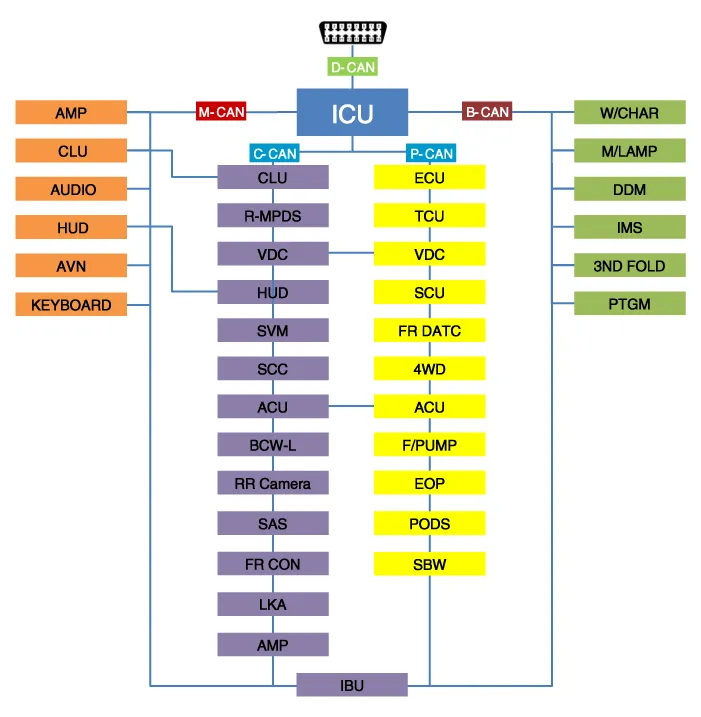
Communication Network Diagram
|
Abbreviation |
Explanation |
|
IBU |
Interated Body Control Unit |
|
DDM |
Driver Door Module |
|
PTGM |
Power Tail Gate Module |
|
ICU |
Interated Control Unit |
|
ECU |
Engine Control Unit |
|
CLU |
Cluster |
|
MDPS |
Moter Driven Power Steering |
|
SVM |
Sorround View Monitor |
|
ACU |
Airbag Control Unit |
|
VDC |
Vehicle Dynamic Control |
|
SCC |
Smart Cruise Control |
|
LKA |
Lane Keeping Assist |
|
BCW |
Blind-Spot Collision Warning |
|
SAS |
Steering Angle Sensor |
|
HUD |
Head up Display |
|
TCU |
Transmission Control Unit |
|
FR DATC |
Dual Automatic Temp Control |
|
4WD |
Four Wheel Drive |
|
F/PUMP |
Fuel Pump Control Module |
|
POCS |
Passenger Occupant Classification System |
|
IMS |
Integrated Memory System |
|
AMP |
Amplifier |
|
AVN |
Head Unit (Audio / AVN) |
|
HUD |
Head Up Display |
|
RR CAMERA |
Rrar View Camera |
|
FR CON |
Front Console Switch |
|
EOP |
Electric Oil Pump |
|
SBW |
Shift BY Wire |
|
W/CHAR |
Wireless Power Chager |
|
FR M/LP |
Front Mood Lamp |
|
3ND FOLD |
3ND Seat Folding Control Unit |
|
AUDIO |
Audio unit |
|
KEY BOARD |
Center Fascia Keyboard |
Circuit Diagram
Removal 1. Disconnect the negative (-) battery terminal. 2. Remove the glove box housing. (Refer to Body - "Glove Box") 3.
Other information:
Hyundai Palisade (LX2) 2020-2026 Service Manual: Rear Evaporator Core
Repair procedures Replacement 1. Remove the rear heater & A/C unit. (Refer to Rear Heater - "Rear Heater Unit") 2. Loosen the mounting screws, remove the rear heater & A/C unit cover (A) and evaporator core (B).
Hyundai Palisade (LX2) 2020-2026 Service Manual: Specifications
Categories
- Manuals Home
- Hyundai Palisade Owners Manual
- Hyundai Palisade Service Manual
- Electrochromatic Mirror (ECM) with homelink system
- Rain Sensor
- Removing and Storing the Spare Tire
- New on site
- Most important about car

Copyright © 2026 www.hpalisadelx.com - 0.0129