Hyundai Palisade (LX2): Integrated Body Control Unit (IBU) / Repair procedures
| Removal |
| 1. |
Disconnect the negative (-) battery terminal.
|
| 2. |
Remove the glove box housing.
(Refer to Body - "Glove Box")
|
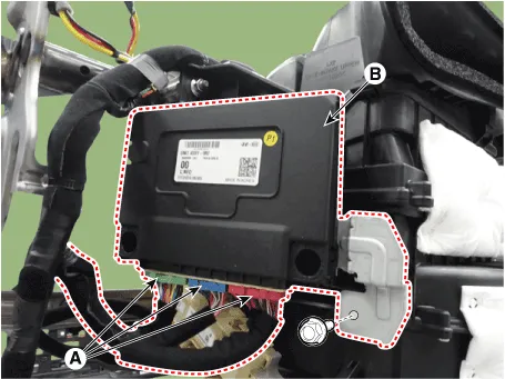
| 3. |
Disconnect the IBU connector (A).
|
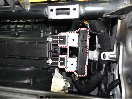
| 4. |
Remove the IBU (B) after loosening mounting bolt and nuts.
|
| Installation |
| 1. |
Install the integrated body control module.
|
| 2. |
Connect the integrated body control module.
|
| 3. |
Install the glove box.
|
| 4. |
Connect the negative (-) battery terminal.
|
| BCM Diagnosis With Diagnostic tool |
| 1. |
In the body electrical system, failure can be quickly diagnosed by using
the vehicle diagnostic system (Diagnostic tool).
|
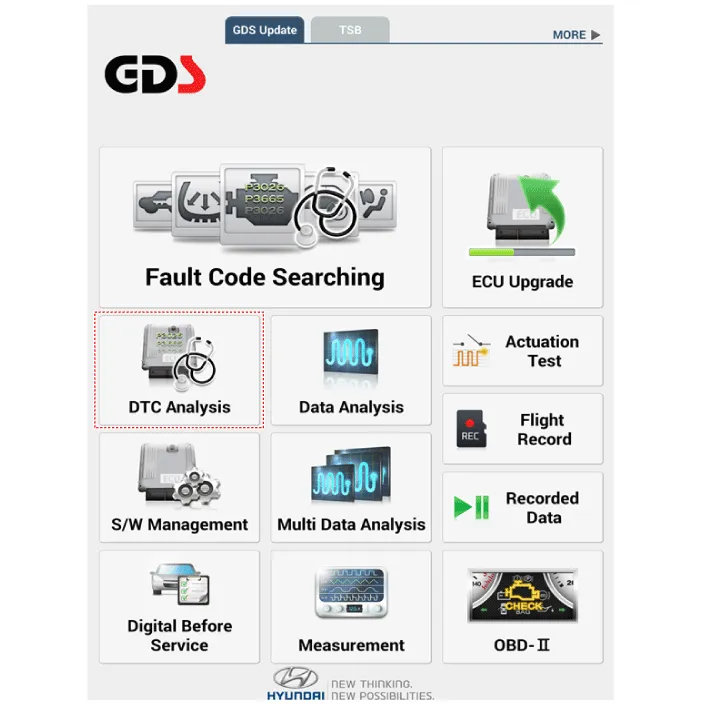
| 2. |
If diagnose the vehicle by Diagnostic tool, select "DTC Analysis" and
"Vehicle".
|
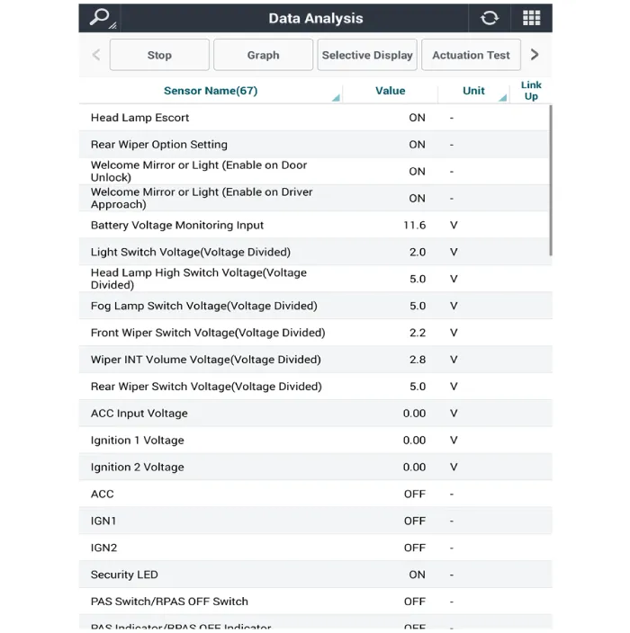
| 3. |
If check current status, select the "Data Analysis" and "Car model".
|

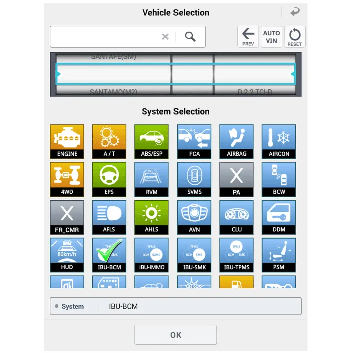
| 4. |
Select the 'IBU_BCM' to search the current state of the input/output
data.
|
Description Body Control Module Controls The Followings – Wiper & Washer Control – Defroster Control – Driving Control – Tailgate Control – Window Control – Interior Control – Exterior Control – Panic alarm Control – MTS – Flasher output Control – Door lock/unlock Control – Burglar alarm Control – Remote start Control – UMS(User Mode Setting) Control – Gateway/ Diagnosis Integrated Body Control Unit (IBU) Integrated body control unit has integrated several functions including body control module (IBU), smart key unit (SMK), and tire pressure monitoring system (TPMS).
Specifications Specifications Memory Power Seat Unit Item Specification Rating voltage DC 12V Operation voltage DC 9V - 16V Operation temperaure -30°C to 75°C parastic current Max.
Other information:
Hyundai Palisade (LX2) 2020-2026 Service Manual: Heater & A/C Control Unit (Rear)
Components and components location Component Connector Pin Function Connector PIN No Pin Function Connector PIN No Pin Function A 1 Battery A 17 IGN2 2
Hyundai Palisade (LX2) 2020-2026 Service Manual: Components and components location
Categories
- Manuals Home
- Hyundai Palisade Owners Manual
- Hyundai Palisade Service Manual
- Emergency liftgate safety release
- Engine Mechanical System
- Resetting the Driver's Seat Memory System
- New on site
- Most important about car
