Hyundai Palisade (LX2): Fuel Delivery System / Delivery Pipe
Repair procedures
| Removal |
|

| 1. |
Release the residual pressure in fuel line.
(Refer to Fuel Delivery System - "Release Residual Pressure in Fuel
Line")
|
| 2. |
Switch "OFF" the ignition and disconnect the negative (-) battery terminal.
|
| 3. |
Remove the air cleaner assembly.
(Refer to Engine Mechanical System - "Air Cleaner")
|
| 4. |
Remove the surge tank.
(Refer to Engine Mechanical System - "Surge Tank")
|
| 5. |
Remove the intake manifold.
(Refer to Engine Mechanical System - "Intake Manifold")
|
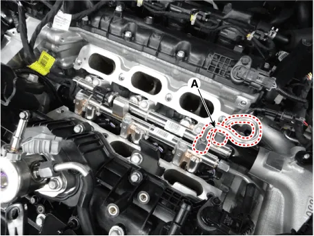
| 6. |
Remove the cross over fuel pipe (A).
|
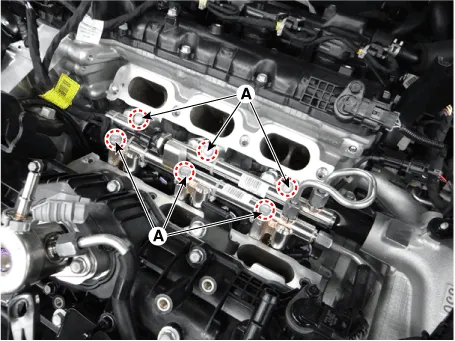
| 7. |
Remove the mounting bolts (A), and then remove the delivery pipe & injector
assembly from the engine.
|
| Installation |
|

|

| 1. |
Install in the reverse order of removal.
|
Repair procedures Removal 1. Turn the ignition switch OFF and disconnect the battery negative (-) cable. 2.
Repair procedures Removal 1. Release the residual pressure in fuel line. (Refer to Fuel Delivery System - "Release Residual Pressure in Fuel Line") 2.
Other information:
Hyundai Palisade (LX2) 2020-2026 Service Manual: Specifications
Hyundai Palisade (LX2) 2020-2026 Service Manual: Description and operation
Description Surround View Monitor (SVM) is the system that allows video monitoring of 360 degrees around the vehicle. The system includes 4 ultra optical camera mounted around the vehicle (front, both sides, rear). The video from these cameras are applied with distortion compensation, time point conversion, and video me
Categories
- Manuals Home
- Hyundai Palisade Owners Manual
- Hyundai Palisade Service Manual
- Rear Heater Unit
- Automatic Transaxle System (A8LF1)
- Convenient Features of Your Vehicle
- New on site
- Most important about car

Copyright © 2026 www.hpalisadelx.com - 0.0175